MicroLogic X Control Unit: Power Supply
Internal and External Power Supplies
The MicroLogic X control unit is powered by the current through the internal current transformers (CT).
oThe standard protection functions of MicroLogic X control units operate with the internal current supply.
NOTE: The earth-leakage protection is powered by the system voltage through the VPS voltage power supply module, installed as standard on MicroLogic 7.0 X.
oIf the load current is higher than 20% of the rated current In, the internal current supply provides the power supply for the full functioning of the MicroLogic X control unit. This includes:
oThe MicroLogic X HMI, display screen and LEDs
oThe metering functions with accuracies in accordance with IEC 61557-12
oThe maintenance and diagnostic functions
oCommunication through ULP modules
oCommunication through Bluetooth low energy
To provide a power supply to the MicroLogic X control unit when the load is below 20% of the rated current In, and maintain the full functioning of the MicroLogic X control unit, optional power supplies can be used. Optional power supplies include the following:
oPermanent power supplies:
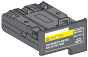
oInternal voltage power supply (VPS) module, up to 600 Vac.
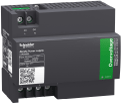
oExternal 24 Vdc power supply.
oTemporary power supplies connected to the mini USB port of the MicroLogic X control unit:
oExternal Mobile Power Pack through USB connection.
oAndroid smartphone through USB OTG connection (smartphone should be compatible with USB OTG - see list of compatible smartphones available on the Schneider Electric website).
oPC through USB connection.
Each optional MicroLogic X power supply is described further.
VPS Voltage Power Supply Module
|
|
|
HAZARD OF ELECTRIC SHOCK, EXPLOSION OR ARC FLASH |
|
oDo not install a VPS module on a network with a voltage above 600 Vac. oTurn off all power supplies upstream and downstream of this equipment before installation and removal. |
|
Failure to follow these instructions will result in death or serious injury. |
|
|
|
DETERIORATION OF VPS MODULE |
|
Disconnect the VPS module by pulling it out to the disconnected position before running a dielectric test on the equipment. |
|
Failure to follow these instructions can result in injury or equipment damage. |
The VPS module is optional for MicroLogic 2.0 X, 3.0 X, 5.0 X, and 6.0 X. It is installed as standard on MicroLogic 7.0 X.

|
The VPS module is installed in the lower part of the MicroLogic X control unit and can be replaced. A green LED on the front face indicates that the VPS module is powered and a 24 Vdc output is supplied. For information about spare part replacement and installation, consult the instruction sheet on the Schneider Electric website: NVE40741 |
|
|
The input voltage of the VPS module is limited to 600 Vac. The module is directly connected to the internal pickup voltage (PTI) on the downstream side of the circuit breaker. |
|
|
The VPS module can be supplied from an external voltage by means of the optional PTE voltage measurement inputs and voltage transformers (mandatory for voltages above 600 Vac). The external voltage can be picked up either from the top or the bottom side of the circuit breaker. When the power source and the PTE option are connected on the same side of the circuit breaker (for example, power source and PTE connected on top side), the MicroLogic X control unit is energized as soon as the power source is live, whatever the position of the circuit breaker (open or closed). |
|
|
When the power source and the PTE option are connected on different sides of the circuit breaker (for example, power source connected on top side and PTE on bottom side), the MicroLogic X control unit is energized only when the circuit breaker is closed. |
The 24 Vdc power supply maintains the operation of all functions of the MicroLogic X control unit in all circumstances, even when the circuit breaker is open and not energized.
The 24 Vdc power supply maintains the functions of the MicroLogic X control unit in low load conditions (load below 20%).
|
NOTICE |
|
LOSS OF DOUBLE INSULATION |
|
oSupply the MicroLogic X control unit with a 24 Vdc SELV (Safety Extra Low Voltage) power supply only, connected through the ULP port module or through the terminal block for external power supply (F1- F2+). Pay attention to the polarity. oDo not connect devices which do not have double insulation to the 24 Vdc SELV power supply which is being used to supply the MicroLogic X control unit. For example, do not use the same 24 Vdc SELV power supply to supply a MicroLogic X control unit for MasterPact MTZ circuit breakers and a MicroLogic A/E/P/H trip unit for MasterPact NT/NW circuit breakers. |
|
Failure to follow these instructions will result in a basic/single insulated system. |
The design of MasterPact MTZ devices with MicroLogic X control units provides double insulation at the front face and for circuit communication lines exiting the device. Double or reinforced insulation is one of the protective measures against electric shock which conforms to IEC and CENELEC HD 60364-4-41 (Low voltage installations - Protection against electric shock).
|
NOTICE |
|
HAZARD OF EQUIPMENT DAMAGE |
|
Use the same 24 Vdc SELV power supply to supply the MicroLogic X control unit and the other ULP modules connected to the ULP port module. |
|
Failure to follow these instructions can result in equipment damage. |
Recommendations for use of external 24 Vdc SELV power supplies:
oThe same 24 Vdc SELV power supply can be used to supply several MicroLogic X control units, depending on the overall power requirements of the system.
oUse a separate 24 Vdc power supply to supply the MN/MX/XF voltage releases or the MCH gear motor.
oUse the same 24 Vdc power supply to supply power to the MicroLogic X control unit and the ULP modules.
oThe 24 Vdc power supply can be used to supply power to the ESM ERMS switch module.
Recommended 24 Vdc Power Supplies
Available 24 Vdc power supplies include the range of Phaseo ABL8 power supplies and the AD power supplies. For more information, refer to the MasterPact MTZ Catalogue.
|
Characteristic |
Phaseo ABL8 power supply |
AD power supply |
|---|---|---|
|
Illustration |

|

|
|
Overvoltage category defined by IEC 60947-1 |
Category II |
oCategory IV per IEC 62477-1 (Vac model) oCategory III per IEC 62477-1 (Vdc model) oCategory III per UL 61010-1 |
|
Input supply voltage AC |
o110–120 Vac o200–500 Vac |
o110–130 Vac o200–240 Vac |
|
Input supply voltage DC |
– |
o24–30 Vdc o48–60 Vdc o100–125 Vdc |
|
Dielectric withstand |
oInput/output: 4 kV RMS for 1 minute oInput/ground: 3 kV RMS for 1 minute oOutput/ground: 0.5 kV RMS for 1 minute |
Input/output: o3 kV RMS for 1 minute (110–130 Vac and 200–240 Vac model) o3 kV RMS for 1 minute (110–125 Vdc model) o2 kV RMS for 1 minute (24–30 Vdc and 48–60 Vdc model) |
|
Temperature |
o50 °C (122 °F) o60 °C (140 °F) with 80% nominal load maximum |
70 °C (158 °F) |
|
Output current |
3 A, 5 A, or 10 A |
1 A |
|
Ripple |
200 mV peak-peak |
200 mV peak-peak |
|
Output voltage setting for line loss compensation |
24–28.8 Vdc |
22.8–25.2 Vdc |
NOTE: For applications requiring an overvoltage category higher than II, install a surge arrester when using a 24 Vdc ABL8 power supply.
If the 24 Vdc power supply is interrupted, a 24 Vdc backup battery can be used to maintain the operation of the MicroLogic X control unit, including wireless communication. It is installed in series between the MicroLogic X control unit and the 24 Vdc power supply module.
The 24 Vdc backup battery must have the following characteristics (compatible with the MicroLogic X control unit):
oOutput voltage 17 V–28.8 Vdc
oCut-off voltage 17 Vdc (24 Vdc backup battery must have a shutdown output voltage in case of low voltage level)
oHysteresis > 3 Vdc (to avoid power-on before the voltage is up to 21 Vdc)
o24 Vdc backup battery should be able to power an Inrush current of 10 A
NOTE: Refer to the table of power consumption to calculate the necessary battery capacity for your installation.

|
The Mobile Power Pack is an external battery that enables power to be supplied temporarily to the MicroLogic X control unit. The Mobile Power Pack enables use of the MicroLogic X display screen and keypad for setting and displaying when the power supply to the MicroLogic X control unit is interrupted. The external Mobile Power Pack can be connected by using a USB cable connected to the mini USB port on the MicroLogic X control unit. |
Check the charge level of the Mobile Power Pack by pressing the test button for one second. The indicator on the Mobile Power Pack lights up to indicate the remaining charge.
NOTE: During periods of setting, commissioning, testing, and maintenance, a smartphone (with USB OTG connection) or a PC connected through mini USB port also provide a temporary power supply.
When no other power supply is supplying the MicroLogic X control unit, the internal battery powers:
oThe trip cause LEDs
oThe service LED
oThe internal clock (date and time)
oThe maintenance schedule function
The following table lists the ULP module consumption:
|
Module |
Typical consumption (24 Vdc at 20 °C/68 °F) |
Maximum consumption (19.2 Vdc at 60 °C/140 °F) |
|
|---|---|---|---|
|
MicroLogic X control unit for MasterPact MTZ circuit breaker |
with external 24 Vdc power supply |
200 mA |
300 mA |
|
supplied through mini USB port |
400 mA |
500 mA |
|
|
supplied through ULP port module |
200 mA |
335 mA |
|
|
M2C programmable contacts |
25 mA |
45 mA |
|
|
ESM ERMS switch module |
25 mA |
45 mA |
|
|
IFE Ethernet interface for one circuit breaker |
100 mA |
140 mA |
|
|
IFE Ethernet switchboard server |
100 mA |
140 mA |
|
|
EIFE embedded Ethernet interface for one MasterPact MTZ drawout circuit breaker |
115 mA |
180 mA |
|
|
IFM Modbus-SL interface or one circuit breaker |
21 mA |
30 mA |
|
|
IO input/output application module for one circuit breaker |
100 mA |
130 mA |
|
|
ULP port module for MasterPact MTZ circuit breaker |
0 mA |
0 mA |
|