Power Factor PF and cos φ Measurement
The control unit calculates:
oThe power factor per phase PF1, PF2, PF3, from the phase active and apparent powers.
oThe total power factor PF from the total active power Ptot and the total apparent power Stot:

NOTE: Stot is the vector or arithmetic total apparent power, depending on the setting.
This indicator qualifies:
oThe oversizing necessary for the installation power supply when harmonic currents are present.
oThe presence of harmonic currents by comparison with the value of the cos φ (see below).
The control unit calculates:
oThe cos φ per phase from the phase active and apparent fundamental powers.
oThe cos φ from the total fundamental active power Pfundtot and the total fundamental apparent power Sfundtot:

This indicator qualifies the usage of the fundamental energy and defines the quadrant of operation. The cos φ is also called the Displacement Power Factor (DPF).
Power Factor PF and cos φ when Harmonic Currents are Present
If the supply voltage is not too distorted, the power factor PF is expressed as a function of the cos φ and the THD(I) by:

The following graph specifies the value of PF/cos φ as a function of the THD(I):
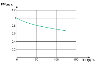
By comparing the 2 values, it is possible to estimate the level of harmonic deformation on the supply.
Sign for the Power Factor PF and cos φ
Two sign conventions can be applied for these indicators:
oIEC convention: The sign for these indicators complies strictly with the signed calculations of the powers (that is, Ptot, Stot, Pfundtot, and Sfundtot).
oIEEE convention: The indicators are calculated in accordance with the following formula:

The following figures define the sign for the power factor PF and cos φ by quadrant (Q1, Q2, Q3 and Q4) for both conventions:
|
IEC Convention |
|
|---|---|
|
Operation in all quadrants (Q1, Q2, Q3, Q4) 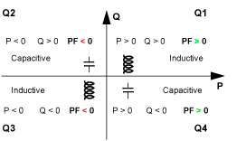
|
Values of cos φ in receiver operation (Q1, Q4) 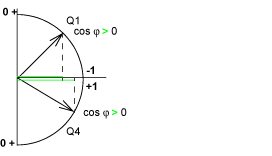
|
|
IEEE Convention |
|
|---|---|
|
Operation in all quadrants (Q1, Q2, Q3, Q4) 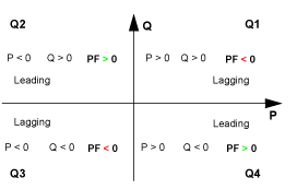
|
Values of cos φ in receiver operation (Q1, Q4) 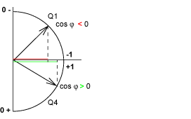
|
NOTE: For a device, a part of an installation which is only a receiver (or generator), the advantage of the IEEE convention is that it adds the type of reactive component to the PF and cos φ indicators:
oLead: positive sign for the PF and cos φ indicators.
oLag: negative sign for the PF and cos φ indicators.
Managing the Power Factor PF and cos φ: Minimum and Maximum Values
Managing the PF and cos φ indicators consists of:
oDefining critical situations.
oImplementing monitoring of the indicators in accordance with the definition of critical situations.
Situations are considered critical when the values of the indicators are around 0. The minimum and maximum values of the indicators are defined for these situations.
The following figure illustrates the variations of the cos φ indicator (with the definition of the cos φ MIN/MAX) and its value according to IEEE convention for a receiver application:
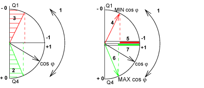
1 Arrows indicating the cos φ variation range for the load in operation
2 Critical zone + 0 for highly capacitive devices (shaded green)
3 Critical zone - 0 for highly inductive devices (shaded red)
4 Minimum position of the load cos φ (lagging): red arrow
5 Variation range of the value of the load cos φ (lagging): red
6 Maximum position of the load cos φ (leading): green arrow
7 Variation range of the value of the load cos φ (leading): green
PF MAX (or cos φ MAX) is obtained for the smallest positive value of the PF (or cos φ) indicator.
PF MIN (or cos φ MIN) is obtained for the largest negative value of the PF (or cos φ) indicator.
NOTE: The minimum and maximum values of the PF and cos φ indicators are not physically significant: they are markers which determine the ideal operating zone for the load.
Monitoring the cos φ and Power Factor PF Indicators
According to the IEEE convention, critical situations in receiver mode on a capacitive or inductive load are detected and differentiated (two values).
The following table indicates the direction in which the indicators vary and their value in receiver mode:
|
IEEE Convention |
||
|---|---|---|
|
Operating quadrant |
Q1 |
Q4 |
|
Direction in which the cos φ (or PFs) vary over the operating range |
|
|
|
Value of the cos φ (or PFs) over the operating range |
0...-0.3...-0.8...-1 |
+1...+0.8...+0.4...0 |
The quality indicator MAX and MIN indicate both critical situations.
According to the IEC convention, critical situations in receiver mode on a capacitive or inductive load are detected but not differentiated (one value).
The following table indicates the direction in which the indicators vary and their value in receiver mode:
|
IEC Convention |
||
|---|---|---|
|
Operating quadrant |
Q1 |
Q4 |
|
Direction in which the cos φ (or PFs) vary over the operating range |
|
|
|
Value of the cos φ (or PFs) over the operating range |
0...+0.3...+0.8...+1 |
+1...+0.8...+0.4...0 |
The quality indicator MAX indicates both critical situations.
Selecting the Sign Convention for the cos φ and Power Factor PF
Set the sign convention for the cos φ and PF indicators as follows:
oOn the MicroLogic X display screen, at Home > Configuration > Measures > PF/VAR Conv.
oWith EcoStruxure Power Commission software.
oBy sending a setting command using the communication network (password-protected).
The factory setting of the sign convention is IEEE.