The Individual Harmonics Analysis Digital Module provides real-time monitoring of individual harmonics of voltages and currents up to rank 40. If harmonic pollution reaches unacceptable levels, it helps you to select appropriate corrective action.
Total harmonic distortions THD(I), THD(V), THD-R(I), and THD-R(V) are calculated as standard by the MicroLogic X control unit.
Individual harmonics are calculated by the MicroLogic X control unit according to the measurement methods specified in IEC 61000-4-30 (Testing and measurement techniques - Power quality measurement methods). The calculation of individual harmonics is performed every 200 ms. The MicroLogic X control unit provides the aggregated values of individual harmonics calculated on a time period of 3 s.
Individual harmonics analysis is available when the Individual Harmonics Analysis Digital Module is purchased and installed on a MicroLogic X control unit.
The Individual Harmonics Analysis Digital Module is compatible with:
oMicroLogic 2.0 X, 5.0 X, 6.0 X, and 7.0 X control units for IEC standard
oMicroLogic 3.0 X, 5.0 X, and 6.0 X control units for UL standard
oMicroLogic X control units with firmware version greater than or equal to 002.000.000. Earlier firmware versions need to be updated.
Data from the Digital Module is available remotely through IFE/EIFE or IFM communication interfaces, if the IFE/EIFE or IFM firmware version is compatible with the Digital Module. For more information, refer to firmware compatibility of the communication interfaces.
|
Measurement |
Unit |
Range |
Accuracy |
Accuracy range |
|---|---|---|---|---|
|
oHarmonics of currents on phase 1 from rank 1 to 40 (40 values) oHarmonics of currents on phase 2 from rank 1 to 40 (40 values) oHarmonics of currents on phase 3 from rank 1 to 40 (40 values) oHarmonics of currents on neutral from rank 1 to 40 (40 values) |
A |
0–20 x In |
5% |
MTZ1: 40–(1,600 x 1.2) MTZ2: 40–(4,000 x 1.2) MTZ3: 80–(6,300 x 1.2) |
|
oHarmonics of phase-to-phase voltage V12 from rank 1 to 40 (40 values) oHarmonics of phase-to-phase voltage V23 from rank 1 to 40 (40 values) oHarmonics of phase-to-phase voltage V31 from rank 1 to 40 (40 values) |
V |
0–1,150 |
5% |
208–690 x 1.2 |
|
oHarmonics of phase-to-neutral voltage V1N from rank 1 to 40 (40 values) oHarmonics of phase-to-neutral voltage V2N from rank 1 to 40 (40 values) oHarmonics of phase-to-neutral voltage V3N from rank 1 to 40 (40 values) |
V |
0–660 |
5% |
120–400 x 1.2 |
|
Measurement |
MicroLogic X HMI |
EcoStruxure Power Device app |
EcoStruxure Power Commission software |
FDM128 |
Communication TCP/IP |
IFE/EIFE webpages |
|---|---|---|---|---|---|---|
|
Magnitude of harmonic n of current phase x (fundamental) |
– |
✔ |
– |
– |
✔ |
– |
|
Magnitude of harmonic n of neutral current (fundamental) |
– |
✔ |
– |
– |
✔ |
– |
|
Magnitude of harmonic n of phase-to-phase voltage Vxy (fundamental) |
– |
✔ |
– |
– |
✔ |
– |
|
Magnitude of harmonic n of phase-to-neutral voltage VxN (fundamental) |
– |
✔ |
– |
– |
✔ |
– |
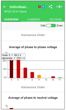
The harmonic spectrum is displayed on the EcoStruxure Power Device app through a Bluetooth or USB OTG connection.
The harmonic spectrum can be exported as a file in JSON format by using the EcoStruxure Power Device app.
Origin and Effects of Harmonics
The presence of multiple nonlinear loads on an electrical network creates harmonic currents in the electrical network.
Harmonic currents distort the current and voltage waves, and degrade the quality of the distributed energy.
If they are significant, distortions can result in:
oDisturbance or degraded operation in the powered devices.
oUnwanted heat rise in the devices and conductors.
oExcessive power consumption.
These various effects increase the system installation and operating costs. It is therefore necessary to monitor energy quality.
A periodic signal is a superimposition of:
oThe original sinusoidal signal at the fundamental frequency (for example, 50 Hz or 60 Hz).
oSinusoidal signals whose frequencies are multiples of the fundamental frequency called harmonics.
oAny DC component.
This periodic signal is broken down into a sum of terms:

where:
oy0: value of the DC component
oyn: RMS value of the nth harmonic
oω: pulsation of the fundamental frequency
oφn: phase displacement of harmonic component n
NOTE: The first harmonic is called the fundamental.
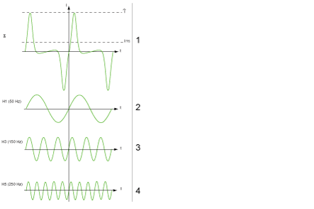
Example of a current wave distorted by a harmonic component:

1 Irms: RMS value of the harmonic waveform
2 I1: fundamental current
3 I3: third order harmonic current
4 I5: fifth order harmonic current
The following screen gives an example of the information available on the EcoStruxure Power Device app.
