The control unit calculates the electrical quantities required for power management:
oThe real-time values of the:
oActive powers (total Ptot and per phase) in kW
oReactive powers (total Qtot and per phase) in kVAR
oApparent powers (total Stot and per phase) in kVA
oThe maximum and minimum values for each of these powers
oThe cos φ and power factor (PF) indicators (total and per phase)
oThe operating quadrant and type of load (leading or lagging)
All these electrical quantities are continuously calculated and their value is updated once a second at rated frequency.
The control unit calculates the power values from the current and voltage samples.
The calculation principle is based on:
oDefinition of the powers
oAlgorithms for the 3-wattmeter calculation method
oSet value of the power sign (circuit breaker powered from upstream (top) or downstream (bottom))
Calculations use harmonics up to the fifteenth.
Total Power Calculation Method
The total reactive and apparent power can be calculated by one of the two following methods:
oVector
oArithmetic (factory setting)
The calculation method can be set as follows:
oOn the MicroLogic X display screen, at Home > Configuration > Measures > Total P calcul
oWith EcoStruxure Power Commission software
3-Pole Circuit Breaker, 4-Pole Circuit Breaker
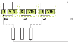
The calculation algorithm is based on the 3-wattmeter method:

When there is voltage measurement on the neutral (4-pole or 3-pole circuit breaker with ENVT wired and configured), the control unit measures the power by using 3 single-phase loads downstream.
When there is no voltage measurement on the neutral (3-pole circuit breaker on power system without neutral) an internal voltage floating reference is used to measure power.
3-Pole Circuit Breaker, Distributed Neutral
Declare the ENVT in the system type setting.
NOTE: Declaration of the ENVT alone does not result in correct calculation of the powers. It is essential to connect the wire from the ENVT to the neutral conductor.
Power Sign and Operating Quadrant
By definition, the active powers are:
oSigned + when they are received by the user, that is, when the device is acting as a receiver.
oSigned - when they are delivered by the user, that is, when the device is acting as a generator.
By definition, the reactive powers have:
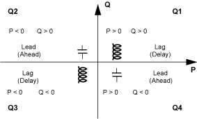
oThe same sign as the active energies and powers when the current lags behind the voltage, that is, when the device is inductive (lagging).
oThe opposite sign to the active energies and powers when the current is ahead of the voltage, that is, when the device is capacitive (leading).
These definitions therefore determine 4 operating quadrants (Q1, Q2, Q3, and Q4):

The sign for the power running through the circuit breaker depends on the type of connection:
oCircuit breakers with the active power flowing from upstream (top) to downstream (bottom) should be set with the power sign P+
oCircuit breakers with the active power flowing from downstream (bottom) to upstream (top) should be set with the power sign P-
Set the power sign convention as follows:
oOn the MicroLogic X display screen, on the screens Home > Configuration > Network > Power sign.
oWith EcoStruxure Power Commission software
oBy sending a setting command using the communication network (password-protected)