Undervoltage Protection (ANSI 27)
Undervoltage protection (ANSI 27) constantly monitors the system voltage. If the voltage level of an installation goes out of its acceptable limits, the information provided by undervoltage protection can be used to initiate appropriate action to restore good operating conditions in the installation.
The information provided by undervoltage protection is used to generate alarms and circuit breaker tripping when required. In addition, the constant monitoring of phase-to-phase or phase-to-neutral voltages enables appropriate action to be initiated to safeguard the operation of the installation during abnormal or critical situations, for example, load shedding, source change-over, and emergency generator starting.
Undervoltage protection is available when the ANSI 27/59 - Under/Over voltage protection Digital Module is purchased and installed on a MicroLogic X control unit.
Undervoltage protection requires an external 24 Vdc power supply.
Undervoltage protection is compatible with:
oMicroLogic 2.0 X, 5.0 X, 6.0 X, and 7.0 X control units for IEC standard
oMicroLogic 3.0 X, 5.0 X, and 6.0 X control units for UL standard
oMicroLogic X control units with firmware version greater than or equal to 002.000.002. Earlier firmware versions need to be updated.
Data from the Digital Module is available remotely through IFE/EIFE or IFM communication interfaces, if the IFE/EIFE or IFM firmware version is compatible with the Digital Module. For more information, refer to firmware compatibility of the communication interfaces.
|
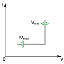
ANSI 27-1 
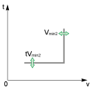
ANSI 27-2 
|
Undervoltage protection monitors either three phase-to-phase voltages (V12, V23, V31), or three phase-to-neutral voltages (V1N, V2N, V3N). Undervoltage protection is of two types: oANSI 27-1: each voltage is monitored independently. The protection picks up when one of three monitored voltages reaches the threshold Vmin1. oANSI 27-2: the three voltages are monitored together. The protection picks up when all three monitored voltages reach the threshold Vmin2. Each type of undervoltage protection, ANSI 27-1 and ANSI 27-2 can be disabled. Both types of undervoltage protection operate according to a settable time delay: oANSI 27-1: the time delay tVmin1 starts as soon as the protection picks up. oANSI 27-2: the time delay tVmin2 starts as soon as the protection picks up. Undervoltage protection operates with a definite time characteristic. NOTE: The selection of voltages to be monitored (phase-to-phase or phase-to-neutral) applies to both undervoltage and overvoltage protections. It is not possible to select different settings for each type of protection. The selection is made for all four types of protection: ANSI 27-1, ANSI 27-2, ANSI 59-1, and ANSI 59-2. |
To inhibit the undervoltage protection (ANSI 27-1 or ANSI 27-2), both the following conditions must be met:
oInhibition is enabled on a specific protection (ANSI 27-1 or ANSI 27-2) by setting the Inhibition parameter to ON.
oInhibition of optional protections is activated by an input of the IO module. The function Inhibit optional protection must be assigned to an input of the IO module.
For more information about inhibiting optional protections, refer to Enerlin'X IO - Input/Output Application Module for One Circuit Breaker - User Guide.
NOTE: The undervoltage protections (ANSI 27-1 or ANSI 27-2) can be inhibited separately, or together.
For undervoltage protection set in tripping mode, the voltage must be measured on the power source side to allow closing of the circuit breaker. As standard, the MicroLogic X voltage input is directly connected to the internal pickup voltage (PTI) on the bottom side of the circuit breaker. So:
oIf the circuit breaker is bottom fed, the internal pickup voltage (PTI) is suitable for undervoltage protection and circuit breaker closing.
oIf the circuit breaker is top fed, an external voltage input is required. The external voltage tap (PTE) option must be used to measure the voltage on the power source side or use the Force to Off when CB is open option.
Setting for All Under/Overvoltage Protections
Select the type of voltages to monitor before making other settings:
oVLL phase-to-phase voltage selection (factory setting)
oVLN phase-to-neutral voltage selection (this setting should be selected only with 4-pole circuit breakers or 3-pole circuit breakers with ENVT wired and configured)
It can be set as follows:
oWith EcoStruxure Power Commission software (password-protected)
oWith EcoStruxure Power Device app (password-protected)
Setting ANSI 27-1 and ANSI 27-2 Undervoltage Behavior Parameter
For a top fed circuit breaker without the PTE option, if the undervoltage protection trips the circuit breaker, it can be difficult to close the circuit breaker again. This is due to the protection detecting the absence of voltage and tripping immediately. To enable closing of the circuit breaker, the undervoltage behavior parameter can be set to Force to Off when CB is open.
The undervoltage behavior parameter, Vmin behavior, has two settings:
oNormal: the protection functions as normal
oForce to Off when CB is open: undervoltage protection is disabled when the threshold is reached and the circuit breaker is in the open position
The settings for undervoltage protection on one phase (ANSI 27-1) are:
oVmin1 mode: enables (ON) or disables (OFF) undervoltage protection on one phase
oVmin1 action: sets the result of undervoltage protection activation as trip or alarm
oTrip: the circuit breaker trips and three events are generated (start, operate, and trip)
oAlarm: two events are generated (start and operate)
oVmin1 inhib: enables (ON) the protection to be inhibited by IO module
oVmin1: threshold of undervoltage protection on one phase
otVmin1: time delay of undervoltage protection on one phase
They can be set as follows:
oWith EcoStruxure Power Commission software (password-protected)
oWith EcoStruxure Power Device app (password-protected)
The dual settings function does not apply to undervoltage protection on one phase. When the dual settings function is enabled, undervoltage protection settings are the same whether set A or set B settings are activated.
The settings for undervoltage protection on all phases (ANSI 27-2) are:
oVmin2 mode: enables (ON) or disables (OFF) undervoltage protection on all phases
oVmin2 action: sets the result of undervoltage protection activation as trip or alarm
oTrip: the circuit breaker trips and three events are generated (start, operate, and trip)
oAlarm: two events are generated (start and operate)
oVmin2 inhib: enables (ON) the protection to be inhibited by IO module
oVmin2: threshold of undervoltage protection on all phases
otVmin2: time delay of undervoltage protection on all phases
They can be set as follows:
oWith EcoStruxure Power Commission software (password-protected)
oWith EcoStruxure Power Device app (password-protected)
The dual settings function does not apply to undervoltage protection on all phases. When the dual settings function is enabled, undervoltage protection settings are the same whether set A or set B settings are activated.
The following are the settings for ANSI 27-1 and ANSI 27-2:
|
Type |
Settings |
Unit |
Setting range |
Step |
Factory setting |
Accuracy |
|---|---|---|---|---|---|---|
|
ANSI 27 ANSI 59 |
Voltage selection |
– |
VLL phase-to-phase/ VLN phase-to-neutral |
– |
VLL phase-to-phase |
– |
|
ANSI 27-1 ANSI 27-2 |
Vmin behavior |
– |
Normal/ Force to Off when CB open |
– |
Normal |
– |
|
ANSI 27-1 |
Vmin1 mode |
– |
ON/OFF |
– |
OFF |
– |
|
Vmin1 action |
– |
Alarm/Trip |
– |
Alarm |
– |
|
|
Vmin1 inhib |
– |
ON/OFF |
– |
OFF |
– |
|
|
Vmin1 |
V |
20–1200 |
1 |
20 |
± 2% |
|
|
tVmin1 |
s |
0–300 |
0.01 |
10.00 |
± 2%, ± 20 ms |
|
|
ANSI 27-2 |
Vmin2 mode |
– |
ON/OFF |
– |
OFF |
– |
|
Vmin2 action |
– |
Alarm/Trip |
– |
Alarm |
– |
|
|
Vmin2 inhib |
– |
ON/OFF |
– |
OFF |
– |
|
|
Vmin2 |
V |
20–1200 |
1 |
20 |
± 2% |
|
|
tVmin2 |
s |
0–300 |
0.01 |
10.00 |
± 2%, ± 20 ms |
Characteristics of undervoltage protection:
oDefinite time delay
oInstantaneous reset time
oHysteresis: fixed 98%
oMinimum breaking time 50 ms
oMaximum breaking time 140 ms with time delay set to 0 s
The function generates the following predefined events:
|
Code |
Event |
History |
Severity |
|---|---|---|---|
|
0x6410 (25616) |
Undervoltage on 1 phase trip |
Trip |
High |
|
0x6210 (25104) |
Undervoltage on 1 phase start |
Protection |
Low |
|
0x6310 (25360) |
Undervoltage on 1 phase operate |
Protection |
Medium |
|
0x642A (25642) |
Undervoltage on all 3 phases trip |
Trip |
High |
|
0x622A (25130) |
Undervoltage on all 3 phases start |
Protection |
Low |
|
0x632A (25386) |
Undervoltage on all 3 phases operate |
Protection |
Medium |
|
0x0EF8 (3832) |
Optional protections inhibited by IO |
Protection |
Low |
|
0x0D0C (3340) |
Config error IO/CU: optional protection Inhibit |
Configuration |
Medium |
Predefined events cannot be modified by the user. For general information about events, refer to Event management.
Protection events are generated as follows:
oThe start event is generated when the protection picks up.
oThe operate event is generated when the protection time delay elapses.
The operate event is not generated when the optional protection is inhibited.
oThe trip event is generated when the circuit breaker tripping voltage release (MITOP) activates.
The trip event is not generated when:
oThe optional protection is set in alarm mode
oThe optional protection is inhibited
|
Code |
Event |
Recommended actions |
|---|---|---|
|
0x6410 (25616) |
Undervoltage on 1 phase trip |
Reset the device or use the Power restoration assistant within the EcoStruxure Power Device app. |
|
0x642A (25642) |
Undervoltage on all 3 phases trip |
Reset the device or use the Power restoration assistant within the EcoStruxure Power Device app. |
|
0x0EF8 (3832) |
Optional protections inhibited by IO |
Check inhibition selector switch wired with IO module. |
|
0x0D0C (3340) |
Config error IO/CU: optional protection Inhibit |
Correct the configuration error with EcoStruxure Power Commission software: oIf you want optional protection inhibition to be controlled by IO module, connect an IO module with inhibit optional protection assignment. oIf you do not want optional protection inhibition to be controlled by IO module, connect an IO module without inhibit optional protection assignment. |
For information about resetting the circuit breaker after a trip due to an electrical fault, refer to the relevant document:
oMasterPact MTZ1 - Circuit Breakers and Switch-Disconnectors - User Guide
oMasterPact MTZ2/MTZ3 - Circuit Breakers and Switch-Disconnectors - User Guide