Setting the Long-Time Overcurrent Protection (L or ANSI 49RMS/51)
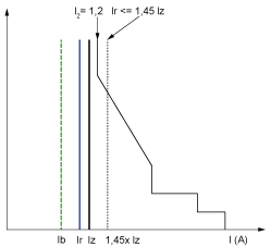
The Ir setting depends on the maximum expected current flow through the breaker and the maximum current that can be withstood by the protected equipment (for example, cables, busbars, generators, and transformers).
The installation rules, such as IEC 60364 Chapter 4.43 or similar national standards, require overload protection for conductors as follows:

Ib Maximal load current
Ir Long time protection setting
Iz Continuous current-carrying capacity of the circuit
I2 Conventional operating current of the circuit breaker = 1.2 x Ir for Schneider Electric electronic control unit
I(A) Current through circuit breaker (phase(s) or neutral)
The tr setting depends on the maximum duration at maximum current and the maximum current that can be withstood by the protected equipment (for example, cables, busbars, generators, and transformers).
Thermal memory: As described in long-time overcurrent protection, this protection function is an overcurrent time-dependent protection with thermal memory. It operates as a thermal image, using the heating and cooling model of a conductor. It can be considered as a first order thermal model with one heating time constant.
The following table shows the relationship between the tr setting and the thermal time constant of the first order thermal model:
|
tr setting (s) |
Unit |
0.5 |
1 |
2 |
4 |
8 |
12 |
16 |
20 |
24 |
|---|---|---|---|---|---|---|---|---|---|---|
|
Equivalent time constant for heating and cooling when control unit is energized |
seconds |
14 |
28 |
56 |
112 |
224 |
335 |
447 |
559 |
671 |
|
minutes |
– |
– |
– |
– |
3.5 |
5.6 |
7.5 |
9.3 |
11.2 |
|
|
Time constant for cooling when control unit is not energized |
minutes |
5 |
||||||||
Summary of tr Setting Guidelines by Application
The following table gives the tr setting guidelines by application:
|
Application |
Principle |
Usual value |
|---|---|---|
|
Secondary side of MV/LV transformer (switchboard main incomer) Tie circuit breaker between two switchboards |
Tripping time according to circuit thermal withstand for busbars, busbar trunking, cable > 240 mm2 (500 MCM): oTime constant > 11 min otr = 24 s When smaller cables are used in parallel, a lower setting should be used. |
tr ≤ 24 s |
|
Generators |
tr ≤ 1 s in order to achieve tripping time < 30 s for 1.5 x Ir (IEC 60034-1 Clause 9.3.2).
|
tr ≤ 1 s |
|
Feeder (cable or busbar trunking protection) |
Tripping time according to circuit thermal withstand for busbars, busbar trunking, cable > 240 mm2 (500 MCM): oTime constant > 11 min otr = 24 s To achieve selectivity with incomer, it can be useful to reduce tr. |
otr ≤ 24 s for busbar trunking or cable ≥ 240 mm² (500 MCM) otr ≤ 16 s for lower cross section cables |
|
Primary side of LV/LV transformer |
According to cable or busbar trunking withstand (transformer withstand is generally higher). To achieve selectivity with incomer, it can be useful to reduce tr. |
otr ≤ 24 s for busbar trunking or cable ≥ 240 mm² (500 MCM) otr ≤ 16 s for lower cross section cables |
|
Power electronic (for example, uninterruptible power supplies, variable speed drives, photovoltaic inverters) |
According to cable or busbar trunking supplying power electronic equipment. |
otr ≤ 24 s for busbar trunking or cable ≥ 240 mm² (500 MCM) otr ≤ 16 s for lower cross section cables |
|
Motors |
If motor is protected against overload by a separate relay, long time setting is done according to circuit thermal withstand. If the MicroLogic control unit is also used for motor thermal overload, motor class must be taken in consideration. |
otr = 12 s for a feeder otr ≥ 8 s for a class 10 motor otr ≥ 12 s for a class 20 motor otr ≥ 16 s for a class 30 motor |
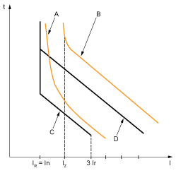
Example of tr setting according to the application:

A Generator thermal limit
B Cable thermal limit
C Protection setting generator tLT (minimum notch)
D Protection setting cable tLT (maximum notch)
Neutral Protection Setting Guidelines
Some indications for setting neutral protection are given here. For more information, refer to the neutral protection section.
The following table indicates the long-time protection settings according to the neutral cable cross section:
|
Cross-sectional area of neutral conductor |
Harmonics expected |
Neutral protection setting |
Long-time protection |
|---|---|---|---|
|
Less than cross-sectional area of phase conductors |
No |
N/2 |
Ir is set according to Iz of cable, Ir applied to neutral is divided by 2 |
|
Equal to cross-sectional area of phase conductors |
No |
OFF |
No harmonics expected: the protection of neutral is not necessary |
|
Yes |
N |
Harmonics expected: the neutral must be protected by the long-time protection, set as for the phase protection |
|
|
Greater than cross-sectional area of phase conductors |
No |
OFF |
No harmonics expected: the protection of neutral is not necessary |
|
Yes |
Oversized N |
Harmonics expected: the neutral must be protected by the long-time protection, set as for the phase protection multiplied by 1.6 (Oversized neutral) |
NOTE: On 3-pole circuit breakers the ENCT option must be declared.
NOTE: In IT systems, a distributed neutral conductor must be protected. Set the neutral protection to N/2, N or Oversized N.