The diagrams are shown with circuits de-energized, all devices open, connected, and charged, and relays in normal position.
Terminals shown in green ( ) must be connected by the customer.
3P or 4P

3P + N

|
Micrologic 5, 6, 7 |
Type |
Item |
Description |
|---|---|---|---|
|
A/E |
Communication |
H(WH) L(BL) |
Data |
|
-(BK) +(RD) |
24 Vdc power supply |
||
|
A/E |
ZSI (Zone selective interlocking) |
Z1 |
Zone selective interlocking OUT SOURCE |
|
Z2 |
Zone selective interlocking OUT |
||
|
Z3(1) |
Zone selective interlocking IN SOURCE |
||
|
Z4(1) |
Zone selective interlocking IN ST (short-time) |
||
|
Z5(1) |
Zone selective interlocking IN GF (ground-fault) |
||
|
A/E |
ENCT |
– |
External neutral current transformer: oShielded cable with 1 twisted pair (T1, T2) oShielding earthed at one end only (CT end) Connection: oL = 30 cm max oMaximum length = 10 m oCable size = 0.4 to 1.5 mm2 oRecommended cable: Belden 8441 or equivalent |
|
E |
ENVT |
– |
External neutral voltage tap for connection to the neutral via a 3P circuit breaker |
|
(1) For Compact NSX400/630 only |
|||
The diagrams are shown with circuits de-energized, all devices open, connected, and charged, and relays in normal position.
Terminals shown in green ( ) must be connected by the customer.
|
With motor mechanism (MT) 
|
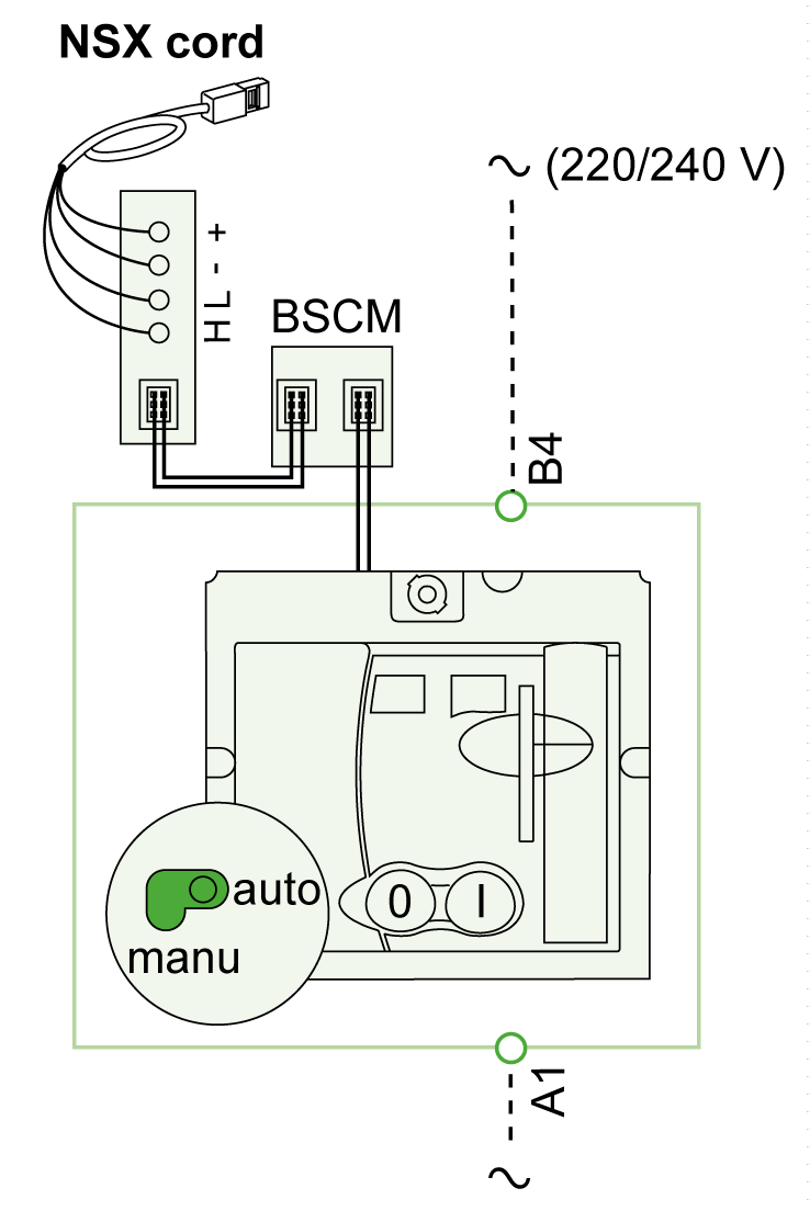
With communicating motor mechanism (MTc) 
|
|
Type |
Item |
Description |
|---|---|---|
|
Voltage release |
MN |
Undervoltage trip release |
|
MX |
Shunt trip release |
|
|
Motor mechanism (MT) |
A4 |
Opening order |
|
A2 |
Closing order |
|
|
B4, A1 |
Motor mechanism power supply |
|
|
L1 |
Manual position (manu) |
|
|
B2 |
SDE interlocking (mandatory for correct operation) |
|
|
BPO |
Opening pushbutton |
|
|
BPF |
Closing pushbutton |
|
|
Communicating motor mechanism (MTc) |
B4, A1 |
Motor mechanism power supply |
|
BSCM |
Breaker status control module |
The diagrams are shown with circuits de-energized, all devices open, connected, and charged, and relays in normal position.
Terminals shown in green ( ) must be connected by the customer.

|
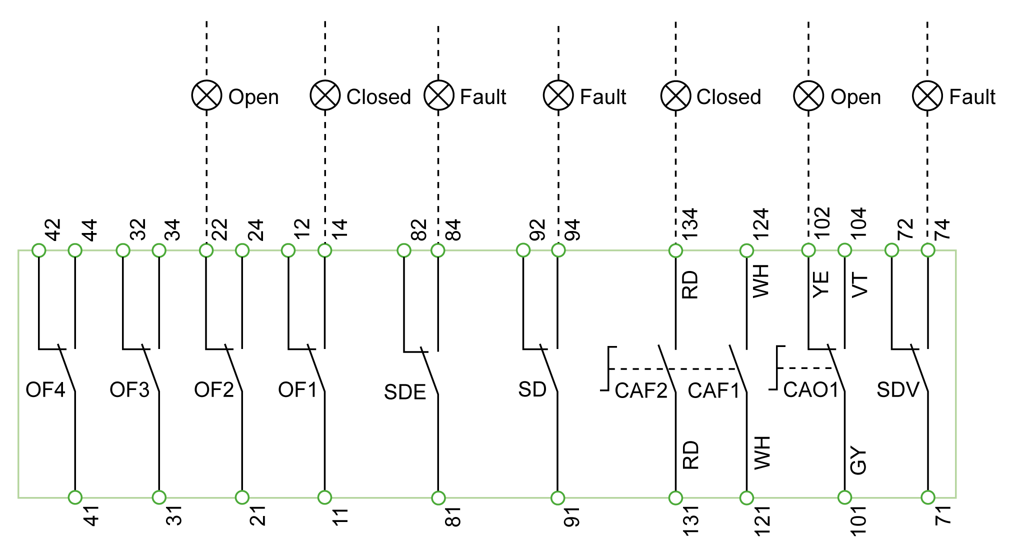
Indication contacts |
Description |
|---|---|
|
OF2/OF1 |
Circuit breaker ON/OFF indication contacts |
|
OF4/OF3 |
Circuit breaker ON/OFF indication contacts (Compact NSX400/630) |
|
SDE |
Fault-trip indication contact (short-circuit, overload, ground-fault, earth-leakage) |
|
SD |
Trip-indication contact |
|
CAF2/CAF1 |
Early-make contact (rotary handle only) |
|
CAO1 |
Early-break contact (rotary handle only) |
|
SDV |
Earth-leakage fault trip indication contact (add-on Vigi module) |
|
Color code for auxiliary wiring |
Description |
|---|---|
|
RD |
Red |
|
WH |
White |
|
YE |
Yellow |
|
VT |
Violet |
|
GY |
Gray |
|
BK |
Black |
|
OR |
Orange |
|
GN |
Green |
|
BL |
Blue |