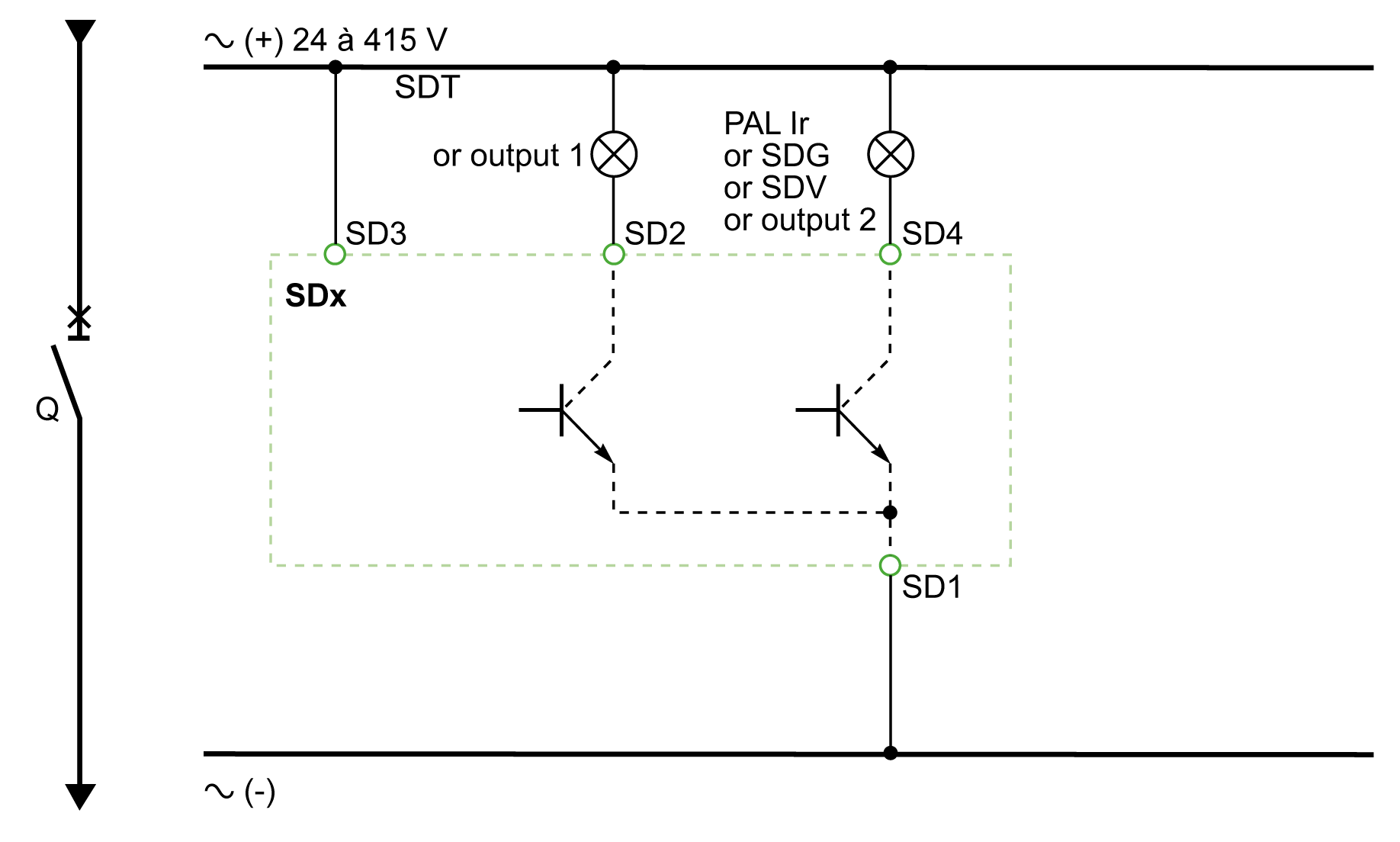
SDx Module With Micrologic 2, 4, 5, 6, and 7 Trip Unit
The diagram is shown with circuits de-energized, all devices open, connected and charged and relays in normal position.
Terminals shown in green ( ) must be connected by the customer.

|
Item |
Description |
|---|---|
|
SD1 SD3 |
SDx-module power supply |
|
SD2 |
Output 1 (80 mA max.) |
|
SD4 |
Output 2 (80 mA max.) |
|
Micrologic |
SD2 |
SD4 |
|---|---|---|
|
Micrologic 2 |
SDT |
– |
|
Micrologic 4 |
SDT |
SDV |
|
Micrologic 5 |
SDT or output 1 |
PAL Ir or output 2 |
|
Micrologic 6 |
SDT or output 1 |
SDG or output 2 |
|
Micrologic 7 |
SDT or output 1 |
SDV or output 2 |

|
Item |
Description |
|---|---|
|
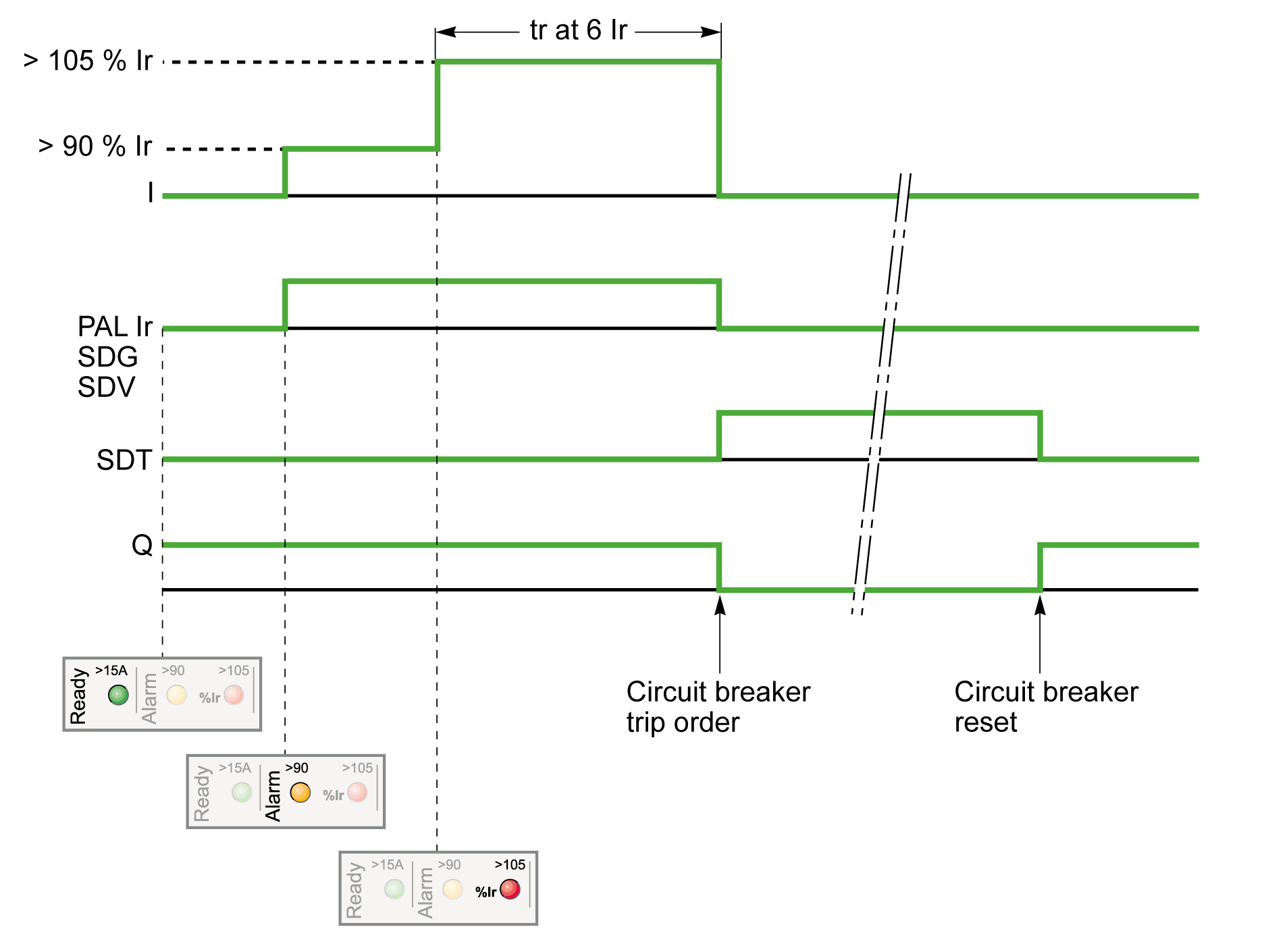
I |
Charge current |
|
PAL Ir |
Thermal overload pre-alarm |
|
SDG |
Ground-fault signal |
|
SDT |
Thermal-fault signal |
|
SDV |
Residual current trip signal (for earth-leakage function) |
|
Q |
Circuit breaker |