Summary of Electrical Auxiliary Devices
The following table shows electrical auxiliary devices that can be added to devices. They can be installed on site. For more information, see the TeSys Motor Control and Protection Components Catalog.
|
Electrical auxiliary device |
Use |
|---|---|
|
OF auxiliary contact |
View the on/off status of the device remotely. |
|
SD auxiliary contact |
View the trip status of the device remotely. |
|
SDE auxiliary contact |
Indicate that the device has tripped on an electrical fault. |
|
AU undervoltage trip release |
Trip the device when the control voltage drops below a tripping threshold. |
|
AS shunt trip |
Send an electrical trip command remotely to trip the device. |
|
SDTAM thermal fault module |
Provide alarm and fault differentiation. |
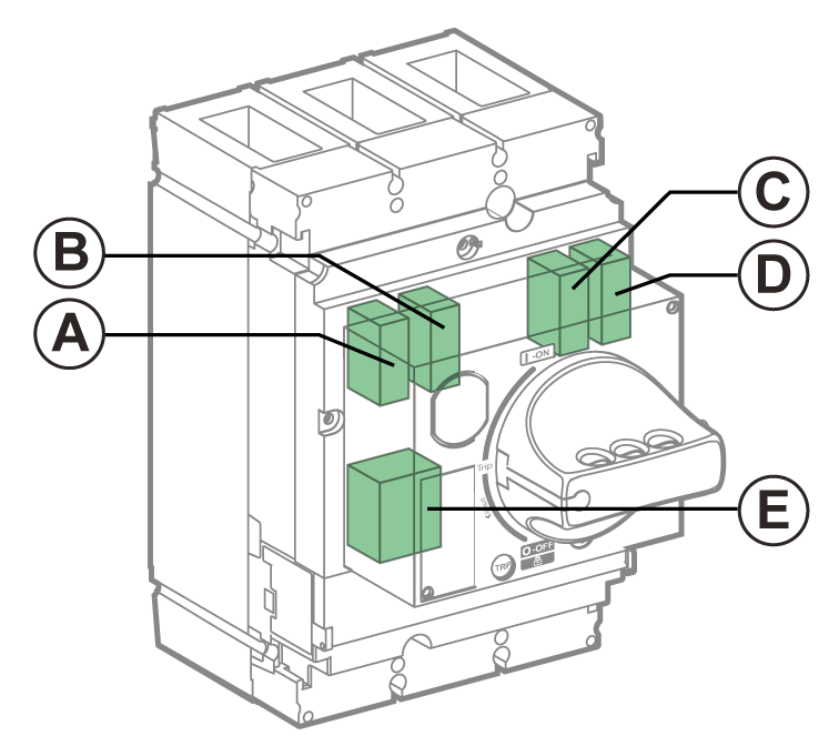
Slots for Electrical Auxiliary Devices on TeSys GV5 Devices
The following table shows the possible slots for electrical auxiliary devices mounted in the case.

|
Electrical auxiliary device |
Slot |
||||
|---|---|---|---|---|---|
|
A |
B |
C |
D |
E |
|
|
OF1 auxiliary contact |
✔ |
– |
– |
– |
– |
|
OF2 auxiliary contact |
– |
– |
– |
✔ |
– |
|
SD auxiliary contact |
– |
✔ |
– |
– |
– |
|
SDE auxiliary contact (with addition of the optional SDE adapter) |
– |
– |
✔ |
– |
– |
|
AU undervoltage trip release |
– |
– |
– |
– |
✔ |
|
AS shunt trip |
– |
– |
– |
– |
✔ |
|
SDTAM thermal fault module |
✔ |
– |
– |
– |
✔ |
NOTE: It is not possible to install all the accessories at the same time in one device. For example, SDTAM thermal fault module uses the same slot as AU undervoltage trip release or AS shunt trip.
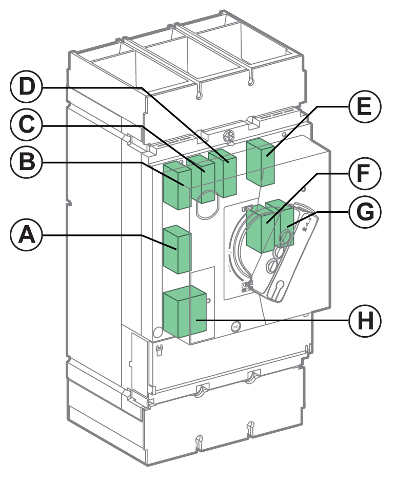
Slots for Electrical Auxiliary Devices on TeSys GV6 Devices
The following table shows the possible slots for electrical auxiliary devices mounted in the case.

|
Electrical auxiliary device |
Slot |
|||||||
|---|---|---|---|---|---|---|---|---|
|
A |
B |
C |
D |
E |
F |
G |
H |
|
|
OF1 auxiliary contact |
– |
✔ |
– |
– |
– |
– |
– |
– |
|
OF2 auxiliary contact |
– |
– |
✔ |
– |
– |
– |
– |
– |
|
OF3 auxiliary contact |
– |
– |
– |
✔ |
– |
– |
– |
– |
|
OF4 auxiliary contact |
– |
– |
– |
– |
– |
– |
✔ |
– |
|
SD auxiliary contact |
– |
– |
– |
– |
✔ |
– |
– |
– |
|
SDE auxiliary contact (with embedded SDE adapter) |
– |
– |
– |
– |
– |
✔ |
– |
– |
|
AU undervoltage trip release |
– |
– |
– |
– |
– |
– |
– |
✔ |
|
AS shunt trip |
– |
– |
– |
– |
– |
– |
– |
✔ |
|
SDTAM thermal fault module |
✔ |
– |
– |
– |
– |
– |
– |
✔ |
NOTE: It is not possible to install all the accessories at the same time in one device. For example, SDTAM thermal fault module uses the same slot as AU undervoltage trip release or AS shunt trip.
Operation of the Auxiliary Indication Contacts
The following table shows the position of the indication contacts (or outputs) relative to the position of the actuator and main contacts.
|
|
Position of the actuator and the main contacts
|
||||||||
|---|---|---|---|---|---|---|---|---|---|
|
ON |
Tripped by: |
OFF |
|||||||
|
AU/AS |
PT(1) |
Trip unit(2) |
|||||||
|
Ir |
Isd |
Ii |
Iunbal |
||||||
|
Name |
Position of indication contacts |
||||||||
|
OF |
✔ |
– |
– |
– |
– |
– |
– |
– |
|
|
SD |
– |
✔ |
✔ |
✔ |
✔ |
✔ |
✔ |
– |
|
|
SDE |
– |
– |
– |
✔ |
✔ |
✔ |
✔ |
– |
|
|
SDTAM - Output 1 (SDT thermal fault indication) |
– |
– |
– |
✔✔ |
– |
– |
✔✔ |
– |
|
|
SDTAM - Output 2 (contactor control) |
– |
– |
– |
✔✔ |
– |
– |
✔✔ |
– |
|
|
✔: Contact closed, ✔✔: Early-make output (400 ms) |
|||||||||
|
(1) PT: Push-to-trip (2) Ir: Overload or thermal protection Isd: Short-time protection Ii: Instantaneous protection Iunbal: Phase-unbalance protection |
|||||||||