Insulation Monitoring Design for ANSI
The following provides information on the design and architecture for an application of the Insulation Monitoring Module in the ANSI market in Canada and United States.
Hardware devices
The following insulation monitoring components are available for all ANSI markets:
Isolated Power Panel
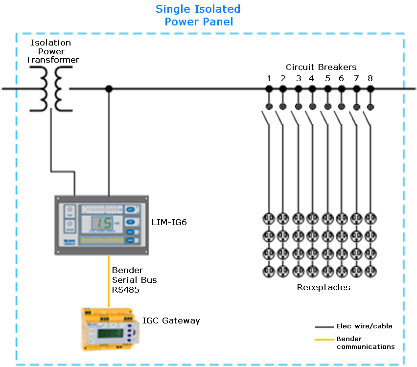
The isolated power panel provides isolated power to electrical systems in critical areas. Panel configurations include a standard single, dual-voltage, and duplex. The single isolated power panel comes with one Iso-Gard™ IG6 line isolation monitor (LIM-IG6) and one power transformer. Dual-voltage panels include two LIM-IG6 devices and one transformer. Duplex panels include two LIM-IG6 devices and two transformers. Other optional devices, including TCP gateways, are available.
Single Isolated Power Panel
The single isolated power panel is a single-voltage, single-system panel. There is no provision for receptacles, ground jacks, or circuit control. This panel contains one LIM-IG6 and one transformer. A TCP gateway and other optional devices are available.
Single Panel with Receptacles and Ground Jacks
The single isolated power panel can be configured with power receptacles and ground jacks on the faceplate of the panel. This panel configuration is suited for areas that require a central location for receptacles and ground jacks.
Dual-Voltage Isolated Power Panel
The dual-voltage isolated power panel provides two different output voltages simultaneously from one isolation transformer. The typical configuration contains the following output voltages:
- One side configured for 208 V or 240 V fixed at 15 kVA.
- Second side configured for 120 V at 5.0, 7.5, or 10 kVA.
This panel type contains two LIM-IG6 monitors, one for each power supply side. Additional components of the dual-voltage panel include:
- 2 reference ground buses
- 1 primary circuit breaker
- 1 secondary main circuit breaker for 120 V side
- 8 branch circuit breakers for 120 V side, field-convertible up to 16
- 1 secondary main circuit breaker for 208 V or 240 V side
- Provision for two 2-pole branch circuit breakers for 208 V or 240 V side.
Duplex Isolated Power Panel
Duplex isolated power panels provide two separate voltage outputs from two isolation transformers. This system is equivalent to two independent single isolated power panels in one enclosure. The duplex panel contains the following:
- 2 single-phase isolation transformers
- 2 LIM-IG6 monitors
- 2 reference ground buses
- 2 primary circuit breakers
- 8 branch circuit breakers for 120 V side, field-convertible up to 16.
Line Isolation Monitor
The LIM-IG6 monitors the impedance to ground of the entire isolated power system. This value is used to calculate the Total Hazard Current (THC), measured in milliamperes (mA). The standard THC alarm value set for line isolation monitors is 5 mA. The value may be switched to 2 mA to meet Canadian Standards Association (CSA) requirements. The LIM-IG6 detects the following information:
- Resistive and Capacitive fault
- Under voltage and over voltage
- Temperature status, when the optional sensor is installed
- Transformer load percentage, when the optional CT is installed
Isolation Power Transformer
To match the requirements for the room branch circuits, the isolation power transformer can be configured with a specific rating and different single-phase primary voltages. A single isolated power panel includes one transformer. A dual-voltage transformer and duplex transformer includes two transformers. See the following table for power rating and primary voltage options.

See the isolation power transformer documentation for wiring diagrams, installation, and other information about the transformer.
IGC Gateway
The IGC gateway, formerly known as COM460IP, can be included in the isolated power panel for data communications. The IGC gateway converts data from the Bender serial BMS protocol to Modbus TCP so the data can be recorded and stored by PME. See the IGC gateway documentation for more information about the gateway.
Branch Circuit Breakers
The isolated power panel includes eight branch circuit breakers for the 120 V side, field-convertible up to 16. Each branch circuit can have up to four single receptacles, so the panel supports up to 64 receptacles. An EDS151 circuit fault monitor can be installed on each branch circuit.
Insulation Fault Locator
The EDS151 insulation fault locator works in conjunction with the LIM-IG6 to detect insulation faults for specific branch circuits in the unearthed power supplies, such as for IT systems. The software can display information about insulation faults when this device is installed.
Circuit Transformers
The SWT3 or SWT4 circuit transformer can be installed for performing load monitoring from the LIMIG6. The software can display information about the transformer load when this device is installed.
- STW3 type current transformers monitor up to 100 A load current.
- STW4 type current transformers monitor up to 200 A load current.
See the SWT3 or SWT4 documentation for more information about the circuit transformers.
Temperature Sensor
A temperature sensor can be installed to monitor the temperature of the isolation power panel. The temperature sensor must be connected to the digital input of the LIM-IG6. The software can display temperature information when this device is installed. See the temperature sensor documentation for more information about the temperature sensor.
Electrical diagrams
This section provides details for electrical connections of the components in the isolated power panel and the hardware configurations that could be commissioned on site. The following figure shows the typical configuration for a single isolated power panel with one 120V isolation transformer, one LIM-IG6 and TCP gateway.

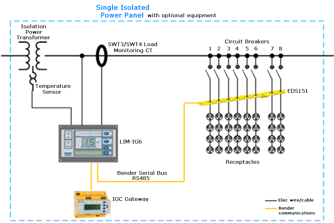
Each isolated power panel can have optional transformer load monitoring, temperature monitoring, and EDS151 or EDS460 circuit fault locators as shown next.

In order to have the transformer load monitoring and circuit fault location, the panel requires these components:
- SWT or SWT4 current transformers. These devices perform transformer load monitoring and are connected to the LIM-IG6 connector plate input 1S1 and 1S2. See the LIM-IG6 documentation for connection details.
- EDS 151 circuit fault locators: Each circuit can have one EDS151 to detect the presence of insulation faults. See the EDS151 documentation for more information.
In the Insulation Monitoring Module, one area can have a maximum of six LIM-IG6 monitors. This enables the following panel combinations:
- 6 single isolated power panels. Each panel has 1 LIM-IG6.
- 3 dual-voltage isolated power panels. Each panel has 2 LIM-IG6.
- 3 duplex isolated power panels. Each panel has 2 LIM-IG6.
Network communication
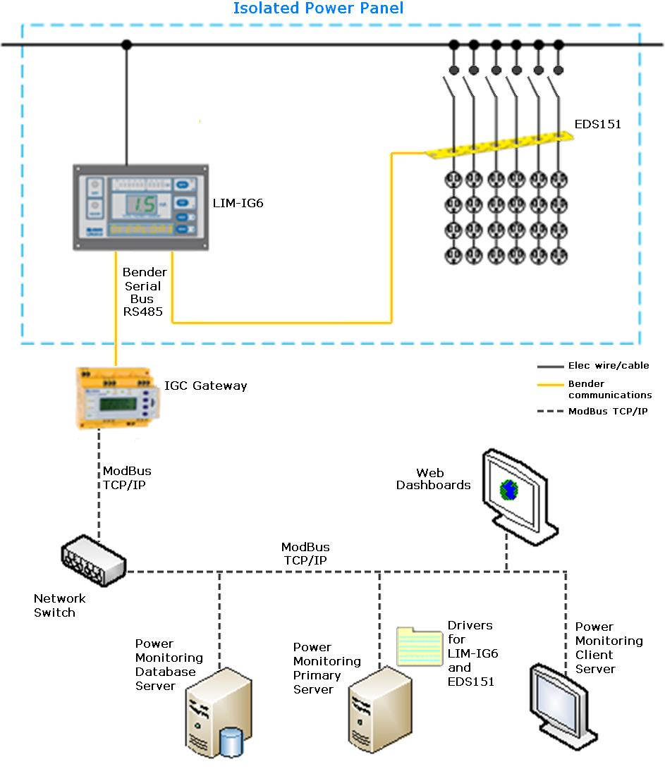
This section shows a network diagram and describes the network communication between the devices in the isolated power panel and the power monitoring system.

This network diagram shows a distributed power monitoring system: the databases are on different servers from the primary server. The system could also have a client server, where users can view their system and generate reports. Other client PCs with dashboards can be included in the system.
The LIM-IG6 is connected to other Bender devices in the isolation power panel using RS485 serial cable. The LIM-IG6 communicates with other Bender devices, such as the EDS151, through the propriety Bender serial bus protocol.
The IGC gateway converts the Bender protocol to Modbus TCP. PME communicates with the IGC gateway through port 502, the standard Modbus TCP/IP port. The software can also connect to the IGC gateway through the Silverlight port 4530. Up to three Silverlight ports can be used simultaneously. See documentation for the IGC gateway for more details.
The LIM-IG6 continuously measures the leakage impedance between isolated line and ground and calculates the Total Hazard Current (THC). When the THC increases to a hazardous level of 5 mA (USA) or 2 mA (Canada), the LIM-IG6 activates alarms internally and on remote devices if available. If an EDS151 is connected to the LIM-IG6, the EDS151 is activated automatically after an alarm is generated by the LIM-IG6. A test signal is sent to the EDS151. The signal flows through the location of the ground fault. Current transformers placed around each sub feeder or load will pick up on this test signal. The EDS151 device will then evaluate the results. The location of the fault is displayed on the EDS151 via an LED bar graph.
All the information above is also available through Modbus TCP protocol. PME gets the real-time data and the event log through Modbus TCP. The software performs software logging every 5 minutes for the following measurements:
- Total hazard current
- Line voltage
- Leakage resistance
- Leakage impedance
- Transformer load monitoring (optional, if SWT3 or SWT4 CT is installed)
- Temperature (optional, if temperature sensor is installed)
When PME is installed on the system, drivers for the LIM-IG6 and EDS151 are installed on the primary server. The Insulation Monitoring Configuration Tool is also installed.