Verify that I/O Devices are Communicating
After the system is configured and communicating in runtime mode, verify that all devices are communicating correctly. All devices that are not communicating will trigger "Communication Failure" alarms, which can be seen in the active alarm log screen. For more information, on how to add this screen to the project, see Adding Alarm Pages. On the Menu Configuration page, use PLSDspShowAlarm(0) as the menu item Menu Command.
Use one of the following methods to test communication.
View the graphics pages
- Create a graphics page containing an appropriate genie selected from the pls_meter library, found in the PLS_Include project.
- Assign the selected genie to the specific device needed to verify communications.
- Save the page and compile the project.
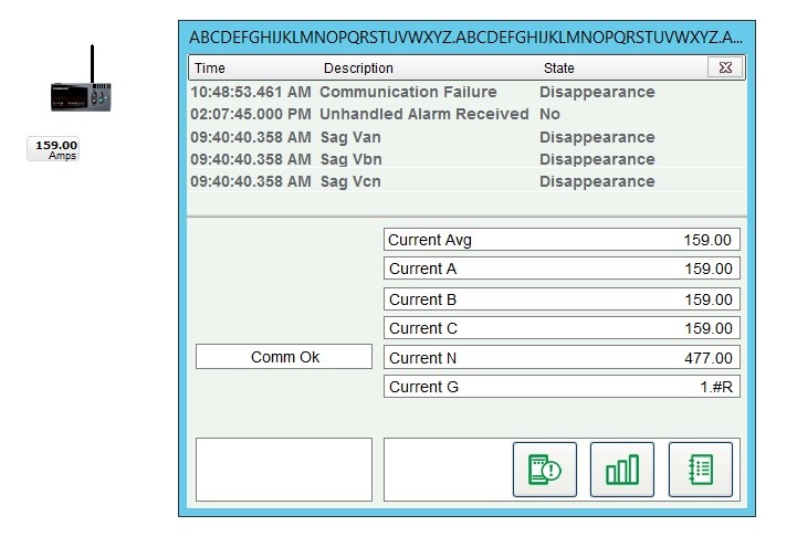
- In the Power Operation Runtime, double-click the genie to open the genie pop-up. Verify that the updated readings displayed by the genie match the actual values on the meter itself. If the readings match, you have verified the device is communicating.
The following image shows a genie and its related genie pop-up:
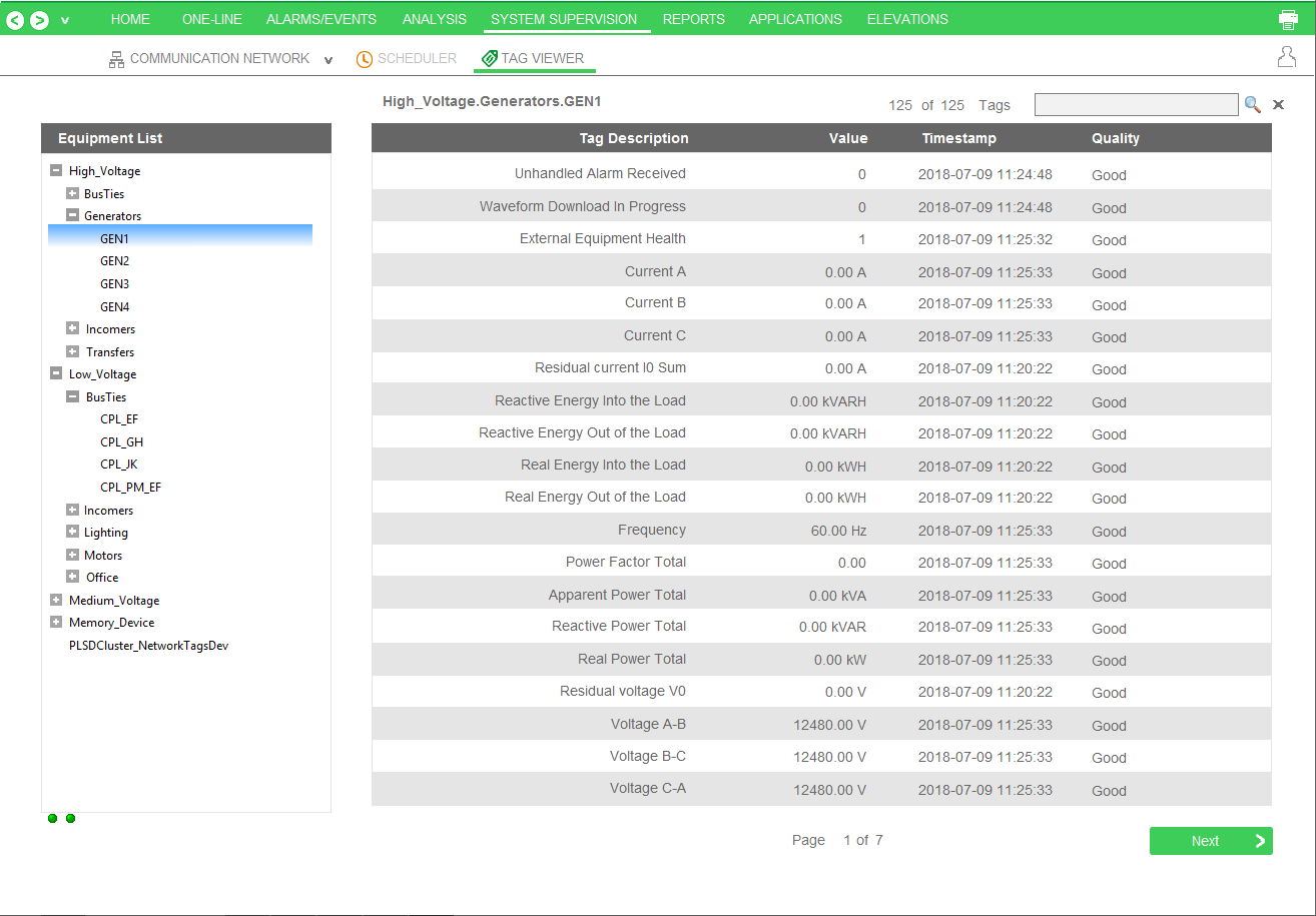
Use the Tag Viewer to learn the status of all project tags
During runtime, open one of the pages that displays real time tag values. The example below is PLSTagView. Compare the values displayed on the Tag Viewer page to actual values displayed on the meter itself. If the compared values match, then you have verified communications with that device.
Use the One-Line Configuration Utility to verify that devices are connected and animations are working
The electrical system must be in a non-critical state so that the breakers being used will not cause any adverse effects (such as putting a person’s safety at risk or affecting a process). Breaker genies should be able to remotely operate the breaker.
![]() danger
danger
equipment electric shock, explosion, or arc flash
| • | Do not rely solely on the display of the graphic on the one-line. |
| • | Use this procedure only during development, and not on a live deployed system. |
| • | Before energizing or de-energizing any equipment from this software, verify that all personnel are a safe distance from all energized equipment. |
| • | Before testing, verify that the proper lock out/tag out procedure is followed, to ensure that the equipment is in an electrically safe condition. |
| • | Ensure that all safety regulations and procedures have been followed before you work on the equipment. |
Failure to follow these instructions will result in death or serious injury.
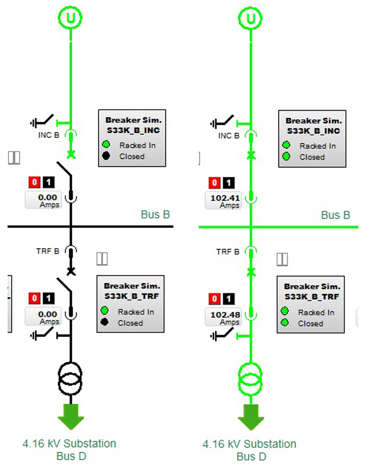
In the Graphics Builder, create a one-line diagram with breaker genies that use the breakers you want to verify. Use the proper logic and passwords to configure the one-line on the diagram. After the diagram is successfully created, open the graphic page in runtime mode.
The breaker genie status indicator should mirror the current breaker state. Also, the busbar color should accurately reflect the electrical state of the conductors connected to the breaker.
The following illustrates the appearance of the one-line drawing with breakers first open and then closed. Note the color change, from black to green (energized), and the position and current changes on the breakers.
Communications Losses
When you bring your system on line, if you find that Power Operation has lost communications with a device, verify the following:
- That the physical connection is correct and secure.
- The IP address.
- The Modbus address.
- statusRegister, statusRegistersCount, and statusRegisterType