Configuring Arc Flash Graphics
![]() warning
warning
inaccurate data results
| ● | Do not incorrectly configure the software or the devices. |
| ● | Do not base your maintenance or service actions solely on messages and information displayed by the software. |
| ● | Do not rely solely on software messages and reports to determine if the system is functioning correctly or meeting all applicable standards and requirements. |
| ● | Consider the implications of unanticipated transmission delays or failures of communications links. |
Failure to follow these instructions can result in death, serious injury, equipment damage, or permanent loss of data.
![]() warning
warning
unintended equipment operation
| ● | Do not use the software or devices for critical control or protection applications where human or equipment safety relies on the operation of the control action. |
| ● | Do not use the software to control time-critical functions. |
| ● | Do not use the software to control remote equipment without proper access control and status feedback. |
Failure to follow these instructions can result in death or serious injury, or equipment damage.
To configure an Arc Flash graphic:
- Open the Graphics Editor.
- Open a single line diagram or other TGML graphic.
- Drag and drop the ArcFlash symbol.
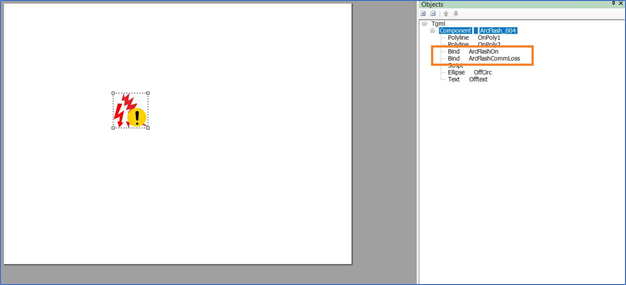
- Select the symbol and then select the Objects pane.
- Edit the Bind values to appropriate names based on the project or field configuration and type of device.
- Select the Properties pane.
- In the Custom section, in the BindForArcFlashCommLoss and BindForArcFlashOn fields, enter the same Bind name values you entered in step 5.
- In the Custom section, enter the values for ValueForArcFlashCommLoss and ValueForArcFlashOn.
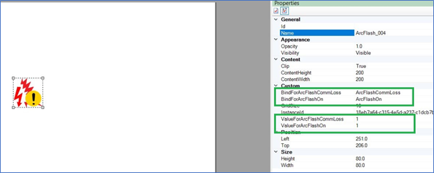
NOTE: To display the arc flash symbol states correctly, configure the device bind values ArcFlashCommLoss and ArcFlashOn to match the respective graphics properties ValueForArcFlashCommLoss and ValueForArcFlashOn values.
- To bind the arc flash component to the respective arc flash field device, use the same binding process as when creating other graphics or advanced one-line components.
NOTE: For more information, see Adding a graphics page in the Graphics Editor or Creating a one-line on a graphics page.
- Select Save.
Displaying Arc Flash States
In the event of an arc flash or an issue with the arc flash monitoring system, a symbol will display next to the device that detected the issue:
| Symbol | State | Description |
|---|---|---|
|
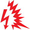
Red arc flash symbol | Arc flash is detected. |
|
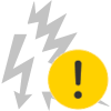
Gray arc flash symbol with yellow exclamation mark. | Any issue with the Arc Flash Monitoring System. |