Linking ION modules
Linking ION modules together is the foundation of programming ION-compliant nodes in Power Monitoring Expert. Although an ION module can perform a function in isolation, the strength and flexibility of the ION architecture comes from the ability to interconnect modules to build more sophisticated functions.
Choosing which ION modules to link
The first step in linking modules is to decide which modules you want to use. When choosing a module to link, you have two choices: you can add and link a new module or you can re-link an existing module.
In some cases, you may not want to add a new module. For example, if all the modules of a particular type are already used, you need to re-link one of them to perform the new function. Most devices are preconfigured at the factory to provide common measurements and calculations. If any of these factory defaults are unnecessary in your application, you can unlink the modules involved and reuse them.
Plan ahead before you add new modules. Unlinked modules are wasted resources.
You may find a linked module that you can use to add a new link, in order to augment the function it is performing. For example, if you have a Setpoint module that triggers a waveform recording, then later decide to use this trigger to reset a counter, you can link that Counter module to the same Setpoint that controls the Waveform Recorder module.
Linking ION modules graphically
Linking modules graphically means pointing and clicking a module’s input, then clicking another module’s output register to link it (note that both input and output register classes must be compatible). You can use this method to link to modules on the same node or to create links across nodes.
You can use the autolinking feature to speed up the process of linking ION modules. Typically, linking ION modules involves connecting the output register of one module to the input of another. In many cases, only one of the module's inputs have the same register class as the selected output register.
If autolinking is enabled, Designer automatically selects the appropriate input and establishes the link. If necessary, it overwrites an existing link. This relieves you from having to manually select the input; however, you cannot see what input you are linking to.
By default, autolinking is disabled. You should only use autolinking if you are thoroughly familiar with all the inputs and output registers of the modules you are working with so that you do not inadvertently create undesirable links.
Enabling autolinking
To enable autolinking, select Options > Enable Autolinking. A check mark beside the option indicates it is selected.
Disabling autolinking
To disable autolinking, clear Options > Enable Autolinking.
Linking ION modules on the same node
If the selected node is a meter such as the
NOTE: To cancel a link-in-progress, click anywhere in the background of the window or press the ESC key.
Linking modules using the point and click method
-
To list a module's output registers, click the output symbol on the right side of the module icon. To list the module's setup registers, hold the CTRL key while clicking the output symbol.
Either a menu opens or, if the module has many registers, a dialog opens listing the available registers.
- Select the register you want to link:
- In the menu, click the register you want to select.
- In the dialog, double-click the register (or click it then click Select).
-
Move the cursor towards the module you want to link to. The cursor changes and a dotted line follows it across the node diagram. This indicates you are in the process of creating a link and it shows where the connecting line will appear in the node diagram.
If you link to a module that is in a different window than the original module (either in a different node diagram or grouping window) the dotted line disappears but the cursor still indicates that a link is in progress.
If the module you want is obscured by another window, click on the title bar of the window containing the module. This brings the window to the foreground without canceling the link. (If you click on the background of the window, the link is cancelled.)
-
Click the input symbol of the module that you want to link to display the module's inputs. Either a menu opens or, if the module has many registers, a dialog opens listing the module's inputs.
If the input is already linked, the label of the register it is linked to is displayed beside the input. If you select the input, the existing link is overwritten.
The inputs that are of a different class than the selected output register are grayed out to indicate you cannot select them.
- Select the input you want to link to:
- In the menu, click the register you want to select.
- In the dialog, double-click the register (or click it then click Select).
- Select File > Send & Save to save your changes to the node.
The procedure described above can also be performed in reverse order. You can select a module's input first and then link it to another module's output register.
Linking modules with variable number of inputs
Some modules, such as AND/OR modules, Data Recorder modules, and Log Acquisition modules have a variable number of inputs. In these cases, when you click on the input symbol, the menu offers one instance of the variable input as well as any fixed inputs the module may have. When linking to one of these modules, you can select the NEW Source item to add a new link or you can select an existing link and overwrite it.
If the two modules are in the same window, the line remains on the screen to show the link between the modules—when you save this change to the node, the line changes from a dotted line to a thin black line to indicate that the link is now programmed on the node.
Linking ION modules across different nodes
If the selected node is a software node, such as the Virtual Processor or Log Inserter, many of the links you create are to modules on other nodes. When you create links across different nodes, it is important to keep track of these links and note what modules are dependent on others. This helps you determine what will happen if you ever want to delete a module that is linked to a module on another node.
NOTE: You cannot link modules on one device to another. For example, you cannot create a link between a module on an
- Open the node diagrams that contain the modules you want to link.
- Position the diagrams within the workspace so you can see the two modules you want to link.
- In the first node diagram, click on the output symbol of the module icon. A menu or dialog opens listing the module's output registers.
- In the list of output registers, click the register you want. (In the case of the dialog, click a register and then click Select.)
- Drag the cursor from the first node diagram to the module you want to link to in the second node diagram. The dotted line ceases to follow the cursor if it crosses the window boundary but the cursor changes to indicate a link is in progress.
- Click on the input symbol of the module icon in the second node diagram. A menu or dialog opens listing the module's inputs. Those that are of a different class than the selected output register are grayed out to indicate you cannot select them.
- Click the input you want, or in the case of the dialog, click the input then click Select. Designer does not graphically represent links between modules on different nodes so you will not see a line connecting the modules.
- Select File > Send & Save to save your changes to the node.
This procedure can also be performed in reverse order. You can select a module's input first and then link it to another module's output register.
NOTE: If the input is already linked, the label of the register it is linked to is displayed beside the input. If you select this input, the existing link is overwritten.
A note about performance
While creating links, you may notice that the circle at the end of the arrow cursor is sometimes black ( ).
).
This indicates that Designer is in the process of retrieving information about a module. You can still click on the inputs or outputs of other modules, but Designer aborts the original request. To minimize the amount of communications between Designer and the connected nodes, avoid unnecessary clicking on the input and output symbols.
If you click on several items in a row, you only see the menu for the last item you click; however, Designer initiates many requests for information, which may impact its performance.
Linking ION modules using the ION tree
In some cases, you may want to use the ION tree to select the register for linking. The ION tree is a hierarchical listing of every node, manager, module, and register in the Power Monitoring Expert network. It allows you to select a register on a node without opening the node diagram. Generally, you use the ION tree to create links across nodes.
The ION tree is also the only way to select registers from devices that are not ION-compliant (and use translators to make data available) such as
Using the ION tree is faster than opening a node diagram. It is useful if you want to link to a register on a node whose diagram has not yet been opened. It is also useful if you want to link to a register, but you are not acquainted with the configuration of the node in which it resides. You can go straight to the register without having to navigate through an unfamiliar node diagram. Also, since a diagram can only be accessed by one user at a time, you can use the ION tree to link to a register on another node where the diagram is already open.
Linking modules using the ION tree
- Click the input symbol of the module icon. A list of the module's inputs is displayed.
- In the list of inputs, select the input you want to link.
-
Click the
 button in the toolbar. (To link a module's setup register, hold the CTRL key while clicking this button.)
The Create Link dialog opens, providing access to the ION tree.
- Specify a node, manager, module and output register: Double-click the node you want in the Nodes box. All managers within the selected node appear in the Managers box. You can then double-click the manager you want, and repeat this procedure for the modules and registers.
- Click OK. The module whose inputs changed appears grayed-out to indicate it is now pending. If both modules are in the same window of the same node diagram, a line appears to represent the link.
- Select File > Send & Save. The new link is established and the module appears programmed.
The procedure described above can also be performed in the reverse order. You can click the button first, select an output register, and then click the input symbol of a module icon to select one of its inputs.
Deleting links
If you want to disassemble a group of linked modules and use them for another function, you can delete the links between the modules rather than deleting the modules. Designer provides several ways to delete links.
Fixed links
Most links between standard modules can be deleted. However, some links between core modules are fixed and cannot be deleted. These fixed links include:
- Data Acquisition module and all Power Meter modules.
- Data Acquisition module and all FFT modules.
- FFT module and all Harmonics Analyzer modules.
- FFT module and all Symmetrical Components modules.
If you attempt to delete a fixed link, Designer informs you that the link cannot be deleted.
Deleting visible links
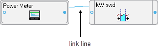
If the linked modules are in the same window, simply click on the link line and press the Delete key. This works well as long as you know which output register and input are involved. For example, in the image below, to delete the link click on the line joining the Power Meter and the Sliding Window Demand module (its color reverses to indicate it is selected) and press Delete.
If there are multiple lines between the same modules and you only want to delete one of the links, you may want to use the method described in Deleting links that are not visible below.
Deleting links that are not visible
If you cannot see a line that links the modules (for example, if they are in different windows), or you need to know which output registers and which inputs are involved, you must use a dialog to delete the link between modules. You can look either at the output register owners of the first module or you can look at the inputs of the second module to see what they are linked to, and then delete the link from there.
Deleting a module's input links
Deleting links at a module's inputs is generally faster than deleting them at the module's output registers because Designer does not need to check the entire node. On the other hand, there is less information available if you view input links. All you see is the label of the output register that is linked to the input. If this is sufficient information, proceed with this method; if not, go to the output registers to delete the link.
Viewing a module's input links
- Right-click the input symbol of the module icon to open the Delete Links dialog.
- Each input and the label of the output register it is linked to are displayed in the dialog. To delete one or more of these links, select the input and click Unlink. The output register label is replaced with dashed lines.
- When you have unlinked all the registers you need to, click OK.
- Select Send & Save to unlink the modules on the node.
Deleting a module's output links
You can also delete links from the Register Owners dialog. This method gives you the most information about the link you are deleting (the output register label and the input and label of the module it is linked to).
Viewing a module's output links
- Right-click the output symbol side of the module icon to open the Register Owners dialog. (To list the module's setup registers, hold the CTRL key while right-clicking on the symbol.)
- Select the output register you want from the Registers section. The Owners section lists all the module inputs to which the selected register is linked.
- To delete one or more of these links, select the module input in the Owners list box and click Unlink. The input name is replaced with a dashed line.
- When you have unlinked all of the module inputs you want, click OK.
- Select Send & Save to unlink the module inputs on the node.
NOTE: Owners that reside on a different node are NOT displayed in this dialog. If you need to delete a link between modules on different nodes, use the procedure described in Deleting a module's input links.