Set up the Generator Battery Health monitoring device
NOTE: The devices used for monitoring the generator electrical data for the Generator Battery Health Report must be able to run an ION framework and must have a V4 input for capturing the battery voltage waveform. Only the following devices meet those requirements:
- ION9000
- ION7650
- ION7550
Other devices cannot be used for this application.
Basic setup
Install and configure the monitoring device. Refer to the device Installation Guide for more information. Obtain the latest version of these documents from Schneider Electric Download Center.
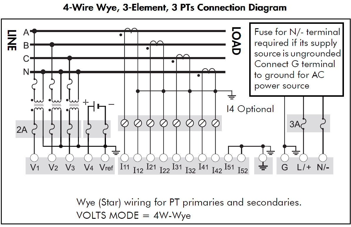
Connect the monitoring device to the generator as follows:
- Connect the digital signal from the generator crank relay to the digital input of the monitoring device. This is the signal that triggers the start of the waveform recording.
- V1 - V3 voltage inputs must have PTs to isolate the ground from the system being monitored and the battery.
- Connect V4 of the monitoring device to the positive side of the battery. Input impedance of V4 terminal, for the devices listed above, is 5 MOhm (phase - Vref).
- Connect Vref on the monitoring device to battery ground.
- Fusing must be installed according to the meter installation instructions.
- Perform a visual inspection of the connections to ensure there is physical separation between the system connected to V1, V2 and V3, and the battery connected to V4.
- For other wiring options with PTs, see the monitoring device Installation Guide.

 danger
electric shock, explosion, or arc flash
Treat the battery circuit as energized to the category of the installation.
Failure to follow these instructions will result in death or serious injury.
Refer to the following diagram as an example for connections to the meter.
Setting up the Battery Health Framework
The Battery Health Framework is designed to capture and record a generator’s battery voltage signature at start up. This voltage signature provides some indication of the health of the generator’s battery bank. A typical waveform capture of the voltage drop when starting is shown next:
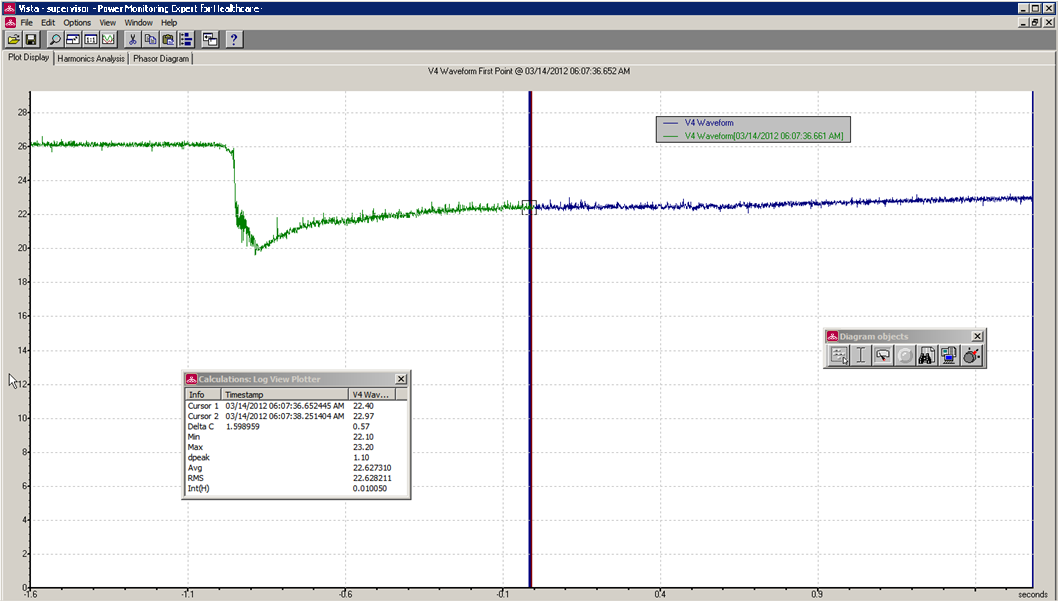
Note the following items about this example:
- This capture shows approximately 4 to 5 seconds' worth of data, accomplished via 3 waveform recorders in series configured at a resolution of 16x96.
- The voltage does not immediately recover to its original value (~26 v) but it begins to ramp up.
- There is about 0.5 seconds of data before the voltage drops to approximately 20 V.
Two options in the framework are possible to capture the waveform, based on how the crank relay signal is triggered - pulse or KYZ.
Example Framework
The following figure shows the typical modules for the framework.
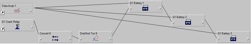
The types of module used are:
- Data Acquisition
- Digital Input
- Convert
- OneShot Timer
- Waveform Recorder
See the following descriptions for the way each module works in this framework.
Refer to ION Reference for details on how each module operates and for setting module parameters.
Data Acquisition – Data Acqn 1

The V4 signal from the meter goes to the Data Acquisition module.
Digital Input – G1 Crank Relay

This module accepts the Cranking Relay signal from the field. When the signal goes high, the logic to record the battery voltage triggers.
The Input mode can be set to Pulse or KYZ, as explained next.
Pulse Input Mode
When the Crank Relay signal goes high, a pulse is generated on the Trigger output register, labeled "G1 Crank Relay." The setup registers for the Digital Input module are shown next.
Note that the Input Mode value is Pulse. The Trigger output can now be fed into the first Waveform Recorder along with V4 from the Data Acquisition module.
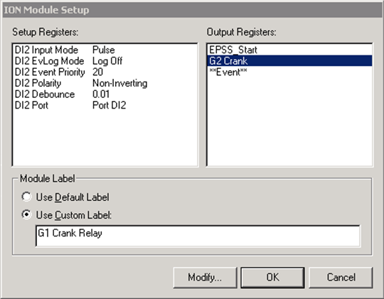
KYZ Input Mode
If you are using the same Digital Input to handle the Generator Start signal (EPSS_Start) it is probably set to KYZ mode.
Input Mode KYZ means that a pulse is generated on the Trigger output register when the Crank Relay signal goes high AND when it goes low. The Convert module and One Shot Timer module (explained later) prevent triggering the downstream logic twice.
The Crank Relay Module is setup like this:
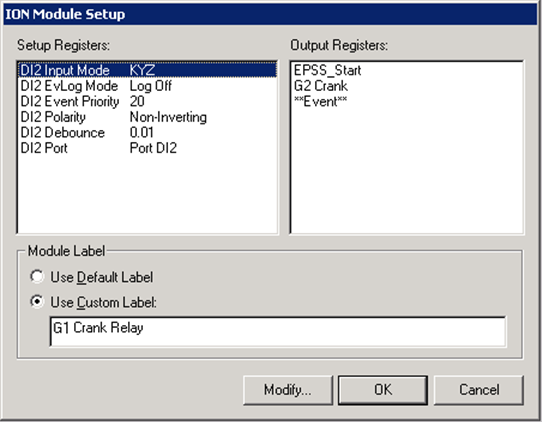
Note that the Input Mode value is KYZ.
Convert
The signal from the Digital Input module cannot be fed directly into the One Shot Timer. The Convert module converts the digital signal to analog for the One Shot Timer.

One-Shot Timer
To prevent triggering the downstream logic twice, send the state (EPSS_Start) from the Convert module into the One Shot Timer:

Send the output register into the first Waveform Recorder G1 Battery 1.
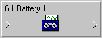
First Waveform Recorder – G1 Battery 1
The Data Acquisition module and G2 Crank Relay module are the inputs to the first Waveform Recorder, labeled “G1 Battery 1.”
These are the setup registers for the module:
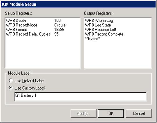
Note the following about the setup registers:
- Depth must be non-zero – 100 is a good number.
- Record Mode should be Circular.
- Format should 16x96. This means 16 samples per cycle and 96 cycles, so at 60 Hz this results in approximately 1.6 seconds' worth of data.
- Record Delay Cycles is set to 95 to allow the “window of observation” to move so that only post-event data is captured. Refer to ION Reference for more details.
Second and Third Waveform Recorders
The second Waveform Recorder - G1 Battery 2 - is cascaded with the first to capture another 1.6 seconds of the battery voltage signature. Do this by using the Record Complete output register on G1 Battery 1 as a flag to trigger G1 Battery 2 to start recording.
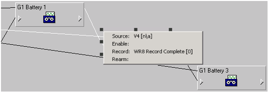
The third Waveform Recorder - G1 Battery 3 - is cascaded with the second recorder to capture the final 1.6 seconds of the battery voltage signature. As above, use the Record Complete output register on G1 Battery 2 as a flag to trigger G1 Battery 3 to start recording.
The Setup Registers should be the same as first waveform recorder with different labels.
Battery Health Waveform Capture results
After the framework is complete, in Vista you should see the voltage signature that looks like the following example image:
After you obtain this type of result, you can configure the generator in the Generator Performance Configuration Tool and define the Battery Health Report.