Data Collection
To decide which architecture is best for data collection, consider the following:
- Device type of the power monitoring devices
- Number of registers to be requested
- Device location
A. Device Type
Which types of power devices are used in the system is the most important aspect to consider when selecting an architecture.
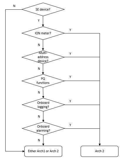
Use the flow chart below to help you with the decision-making process:

Descriptions:
SE (Schneider Electric) device
Most of the SE meters and circuit breakers are supported in PME by default. In addition, a large number of add-on device drivers for PME can be downloaded from the Exchange community. For those device types that are not supported by existing drivers, you can create custom drivers with tools provided by PME. The commissioning time is reduced when there are pre-existing drivers for your device types in PME.
Building Operation has SmartWidgets for some of the SE power devices. For those device types that are not supported, you must perform manual mapping in order to communicate to the device. The commissioning time is reduced when there is a SmartWidget for your device.
NOTE: If the device uses a protocol other than Modbus, further investigation on gateways might be needed before choosing a communication architecture.
ION meter
ION meters use ION protocol, which is supported by PME but not by Building Operation. Therefore, it is required to connect these meters to PME (à Architecture 2).
NOTE: Most of the ION meters also support Modbus protocol. However, advanced functions, such as waveforms, on-board logging or on-board alarms, are not available through Modbus communication. Therefore, connecting an ION meter through Modbus is not recommended.
Multi-address device
A Multi-address device is a Modbus device that has multiple Modbus IDs, such as the Masterpact. Multi-address devices are supported in PME but not in Building Operation. In Building Operation, multiple Modbus devices need to be created for each multi-address device, because each Building Operation device can only have one Modbus ID. This increases the complexity of the system tree structure and requires more commissioning time and effort as compared to PME (à Architecture 2).
PQ (Power Quality) functions
If the devices have PQ functions and you want to make use of these functions, Architecture 2 is recommended because PME provides access to events, waveforms, reports, and all other power quality related information (à Architecture 2).
On-board logging
If the devices have on-board logging functions, Architecture 2 is recommended because PME can retrieve the on-board logs instead of doing software-based logging, like Building Operation (à Architecture 2).
NOTE: On-board data logging is typically more reliable and more accurate than software-based logging.
On-board alarming
If the devices have on-board alarming functions, Architecture 2 is recommended because PME can retrieve the on-board alarms instead of monitoring the values and generating alarms in the software, like Building Operation (à Architecture 2).
NOTE: On-board alarming is typically more reliable and more accurate than software-based alarming, which is particularly important for power failure root cause analysis.
Conclusion:
For many applications, Architecture 2 is the better choice with regards to power monitoring device types. However, when only low-end power meters, energy meters, or pulse meters are used, there is no difference between the two architectures.
B. Number of Registers to be Requested
If only kWh and a few power measurements are needed from a device, then either Architecture 2 or Architecture 1 can be used, as long as the existing Automation Server can handle the Modbus serial loop communication of the power devices.
However, if many measurements are needed for each power device, we recommend you use Architecture 2 to keep communication of the power devices separated from the building automation devices.
C. Device Location
Consider the device location and communication network layout when choosing an architecture. If all power devices are located together in the electrical room, then we recommend you use communication gateways, such as the Link150, to connect them with dedicated daisy chains. However, when a limited number of devices is located close to an Automation Server, it might be to connect them directly to that server.
TIP: Since you can combine the two architectures, choose the most convenient way to connect to the devices.