Setting up your network in Management Console
![]() warning
warning
inaccurate data results
| ● | Do not incorrectly configure the software or the devices. |
| ● | Do not base your maintenance or service actions solely on messages and information displayed by the software. |
| ● | Do not rely solely on software messages and reports to determine if the system is functioning correctly or meeting all applicable standards and requirements. |
| ● | Consider the implications of unanticipated transmission delays or failures of communications links. |
Failure to follow these instructions can result in death, serious injury, equipment damage, or permanent loss of data.
![]() warning
warning
unintended equipment operation
| ● | Do not use the software to control time-critical functions. |
| ● | Do not use the software to control remote equipment without proper access control and status feedback. |
Failure to follow these instructions can result in death, serious injury, or equipment damage.
notice
Network inoperability
Do not make unauthorized changes in the network configuration.
Failure to follow these instructions can result in an unstable or unusable network.
The Primary Server contains all the Power Monitoring Expert programs and it controls the overall operation of your energy management system. The primary server is displayed on the Server screen when you first start Management Console.
To start building your system, add and configure your sites and devices.
Overview
Site and Device Naming restrictions
The following applies to Site, Device Group, and Device Name naming:
- Names cannot contain spaces or the following characters: \ / : * ? " < > { } . , ' & @ | % #
- The maximum length for a
Group.Devicename is 99 characters (+ 1 for the period separation). - Do not use names such as CON, AUX, COM1, and LPT1 for sites and devices.
- All characters must exist in the system's Windows code pages. For example. on an English Windows operating system, certain non-English language characters are not supported.
Adding network components
For details on adding various components, see the following sections.
Follow the procedure below to add a new network component:
- In the System Setup pane, select the icon for the type of item that you want to add ( Site, Device, or Dial Out Modem).
-
Right-click the display window, select New, and then select the specific type of network component from the shortcut menu to open the Configuration dialog.
The options differ depending on which system setup icon you selected.
- Use the fields and drop-down menus to configure properties. Mandatory items are highlighted in red. To configure advanced properties, right-click the dialog and select Advanced Properties. For more shortcut menu options, see Configuration Dialog shortcut menus, below.
- Click OK to add the component.
Configuration Dialog shortcut menus
Right-click the Configuration dialog to access the following shortcut menu options:
- Property Details: This opens a window that contains information on the selected property, including minimum and maximum allowable values, if applicable.
- Advanced Properties: This exposes all the property fields that are hidden in the default (basic) view. For further information about the Time synchronization option. see Time synchronization for ION meters for further information.
- Reset All To Default: Resets all properties to their original values.
Adding a server
Click the Servers icon, right-click the display window and select New > Computer. Fill in the mandatory Name field.
Adding devices
Setting Up devices for direct serial communications
To set up devices for RS-232 or RS-485 communications on a direct serial loop, first add a direct site in Management Console and specify a serial communications port on the computer.
Step 1: Adding a direct site
Click the Sites icon. Right-click the display window and select New > Direct Site. Fill in the Name and Serial Port fields. Configure the other fields as you require.
Step 2: Adding a device to the direct site
Click the Devices icon. Right-click the display window and select New > Serial Device on Direct Site. Fill in these fields:
- Group: Type a name for the group or select an existing group from the list.
- Name: Type the name you want to give the device.
- Device Type: Select the type of the device.
- Unit ID: Type the Unit ID of the device; the range is 1-9999 for
- Site: Select the direct site you previously set up.
- Time Zone: Select the timezone you want the device data to be displayed in, in the software. This setting is only used for the display of timestamped data in the software. It does not affect the configuration of the monitoring device itself.
Configure the other fields as you require.
Setting up devices for Ethernet gateway communications
To set up devices for Ethernet gateway communications, first add and configure an Ethernet gateway site. Ethernet gateways that can be used include those that are simple Ethernet-to-Serial converters, or any gateway or data concentrator that provides ModbusTCP communications.
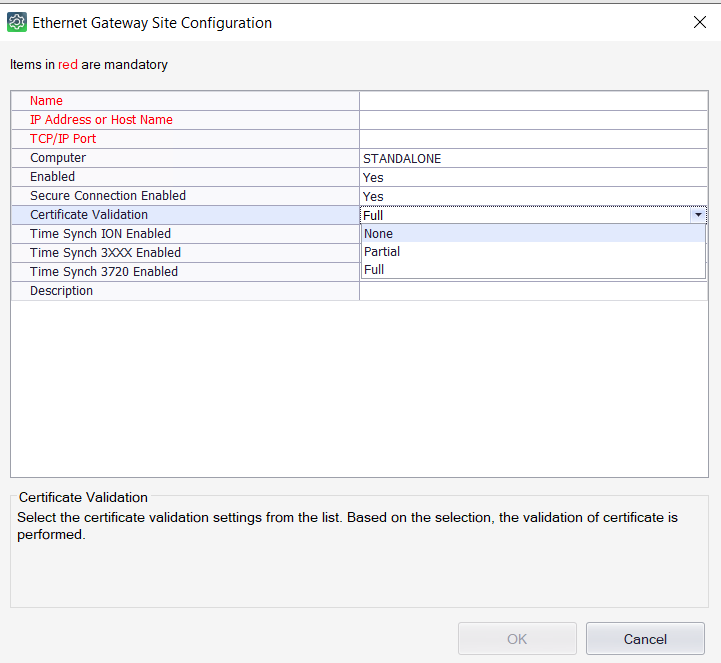
Step 1: Adding an Ethernet gateway site
Click the Sites icon. Right-click the display window and select New > Ethernet Gateway Site.
Complete the Name, IP Address or Host Name, TCP/IP Port, and Secure Connection Enabled fields. (The IP address can be IPv4 or IPv6.) The TCP/IP Port identifies which communications port is used to connect to the serial devices. The port you use depends on the type of Ethernet gateway you want to set up (use 7801 for an EtherGate gateway via COM1 or use port 502 for a Modbus gateway).
NOTE: Secure Connection Enabled must be enabled only when the selected device supports Secure ION or Modbus Encryption.
Configure the other fields as you require.
If you select Secure Connection Enabled, select one of the following Certificate Validation types:
- Full: PME performs Certification checks. If there are issues with the certificate, PME notifies certificate status, and then blocks the communication to the meter.
- Partial: PME performs Certification checks. If there are issues with the certificate, PME notifies certificate status, and then connects to the device.
- None: PME does not perform Certification checks while establishing a TLS connection.
Step 2: Adding a Device to the Ethernet Gateway Site
Click the Devices icon. Right-click the display window and select New > Serial Device on Ethernet Gateway Site. Fill in these fields:
- Group: Type a name for the group or select an existing group from the list.
- Name: Type the name you want to give the device.
- Device Type: Select the type of device.
- Unit ID: Type the Unit ID of the device; the range is 1-9999 for
- Site: Select the Ethernet gateway site you previously set up.
- Time Zone: Select the timezone you want the device data to be displayed in, in the software. This setting is only used for the display of timestamped data in the software. It does not affect the configuration of the monitoring device itself.
Configure the other fields as you require.
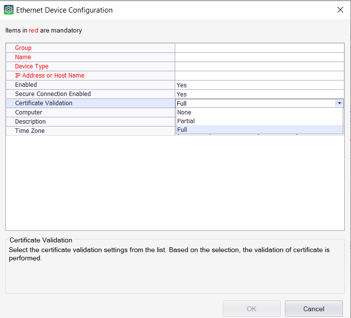
Adding an Ethernet device
Ethernet devices are configured in PME by providing fixed IP addresses (IPv4 or IPv6) and ports, or based on device names. Device names must be used for devices with dynamic address assignment, for example using the DHCP protocol. When device names are used, then a form of name resolution mechanism is required on the network.
To add an Ethernet device, click the Devices icon. Right-click the display window and select New > Ethernet Device. Fill in the Group, Name, Device Type, IP Address or Host Name, Secure Connection Enabled, and Time Zone fields. (The IP address can be IPv4 or IPv6.) Configure the other fields as you require.
NOTE: For the Time Zone field, select the timezone you want the device data to be displayed in, in the software. This setting is only used for the display of timestamped data in the software. It does not affect the configuration of the monitoring device itself.
NOTE: Secure Connection Enabled must be enabled only when the selected device supports Secure ION or Modbus Encryption.
If you select Secure Connection Enabled, select one of the following Certificate Validation types:
- Full: PME performs Certification checks. If there are issues with the certificate, PME notifies certificate status, and then blocks the communication to the meter.
- Partial: PME performs Certification checks. If there are issues with the certificate, PME notifies certificate status, and then connects to the device.
- None: PME does not perform Certification checks while establishing a TLS connection.
Setting up devices for OPC communications
To set up devices for OPC communications, first add an OPC site.
Step 1: Adding an OPC site
Click the Sites icon. Right-click the display window and select New > OPC Site. Fill in the Name and Address fields. Configure the other fields as you require.
Make sure you follow the correct syntax when typing in the address for the OPC site. Select the Address field to see an example address in the Property Description section (near the bottom of the OPC Site Configuration dialog).
Step 2: Adding a device to the OPC site
NOTE: At least one OPC Device Type needs to be preconfigured before an OPC Device can be created in Management Console. Contact Technical Support for assistance.
Click the Devices icon. Right-click the display window and select New > OPC Device. Fill in the Group, Name, Device Type, Site (select the OPC site you previously set up), and Time Zone. Configure the other fields as you require.
NOTE: For the Time Zone field, select the timezone you want the device data to be displayed in, in the software. This setting is only used for the display of timestamped data in the software. It does not affect the configuration of the monitoring device itself.
Adding a modem
- Click the Dial Out Modems icon, right-click the display window and select New, then select either Serial Modem (hardware modem) or WinModem (Windows modem).
- Fill in the values for the mandatory fields:
- For Serial modem, select the Modem Type from the list. If your modem is not in this list, select “Generic ION Modem - Other”. Select the Serial Port where your modem is connected.
For WinModems, select the Modem Name from the list.
Configure the other fields as you require.
- Click OK.
WinModem installation notes
Before you can use a WinModem, you must first install it on your computer (follow the instructions that came with the WinModem product). After you restart the computer, set up the WinModem:
- In Microsoft Windows, click Start > Settings > Control Panel, then double-click Phone and Modem Options.
- Click the Modems tab, select your WinModem, then click Properties.
- Click the Advanced tab, then click Change Default Preference.
- Set Port speed to match the baud rate that is used between the meter and the modem on the remote end of the connection (both modems must be set to the same baud rate).
- Set Flow Control to “None”.
- Click OK to save your changes.
NOTE: You may need to restart your computer for the settings to take effect.
Editing a network component
- Click the icon in the System Setup pane for the type of component you want to edit.
-
In the display window, right-click the network component you want to edit and select Configure <Network Component> (with <Network Component> being the type of component you want to edit).
You can rename devices or groups displayed in the Devices pane without selecting the Configure option.
NOTE: If you rename a group or device, the data that is already stored in the database is associated with the new group or device name. New data will be added to the database using the new name.
- Make the required changes. To display all configurable fields, right-click the Configuration dialog and select Advanced Properties.
- Click OK when you are finished to save your changes.
Deleting a network component
- Click the System Setup icon for the type of component you want to delete.
- In the display window, right-click the network component you want to delete and select Delete (or select the item and press the DELETE key).
- Click Yes to confirm the deletion or No to cancel.
NOTE: When you delete a Site or a Server, all devices associated with it are also deleted.