Set up the UPS Battery Health monitoring device
NOTE: The devices used for monitoring the UPS electrical data for the UPS Battery Health Report must be able to run an ION framework and must have a V4 input for capturing the battery voltage waveform. Only the following devices meet those requirements:
- ION9000
- ION7650
- ION7550
Other devices cannot be used for this application.
Basic setup
Install and configure the monitoring device. Refer to the device Installation Guide for more information. Obtain the latest version of these documents from Schneider Electric Download Center.
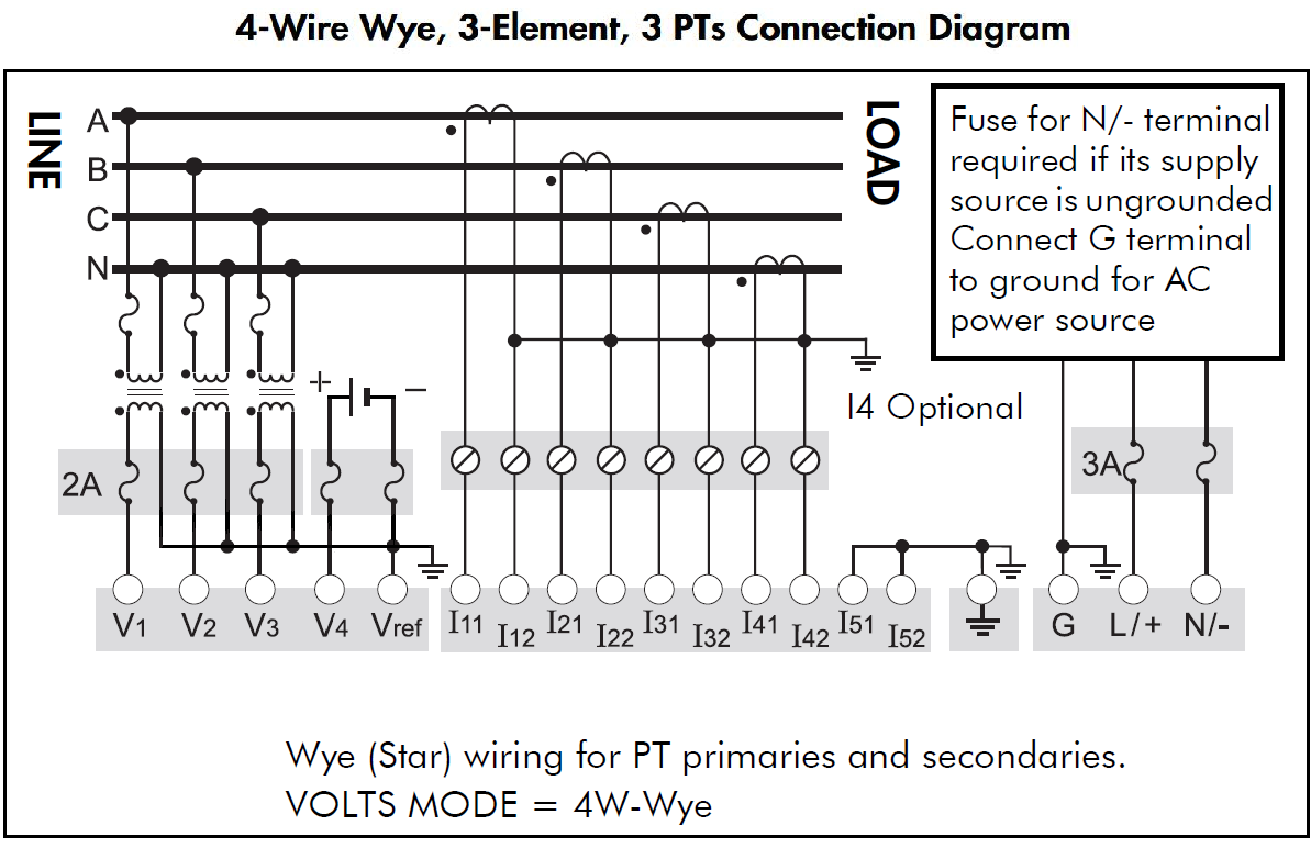
Connect the monitoring device to the UPS as follows:
- Connect V1 - V3 to the UPS outputs. The voltage inputs must have PTs to isolate the ground from the system being monitored and the battery.
- Connect V4 of the monitoring device to the positive side of the battery. Input impedance of V4 terminal, for the devices listed above, is 5 MOhm (phase - Vref).
- Connect Vref on the monitoring device to battery ground.
- Fusing must be installed according to the meter installation instructions.
- Perform a visual inspection of the connections to ensure there is physical separation between the system connected to V1, V2 and V3, and the battery connected to V4.
- For other wiring options with PTs, see the monitoring device Installation Guide.

 danger
electric shock, explosion, or arc flash
Treat the battery circuit as energized to the category of the installation.
Failure to follow these instructions will result in death or serious injury.
Refer to the following diagram as an example for connections to the meter.
Setting up the UPS Battery Health framework
The UPS Battery Health framework is designed to capture and record a UPS’s battery voltage signature at start up. This voltage signature provides some indication of the health of the UPS’s battery bank. A typical waveform capture of the voltage drop when the UPS comes online is shown below:
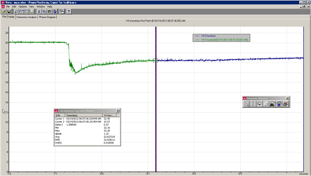
Note the following items about this example:
- This capture shows about 4 - 5 seconds' worth of data, accomplished via one (1) waveform recorder configured at a resolution of 512 x 4.
- The voltage does not immediately recover to its original value but it begins to ramp up.
- There is about 0.5 seconds of data before the voltage drop to approximately 20 V.
To paste the framework into the ION monitoring device:
- Open Designer and open the device node of the monitoring device.
- Drag a Grouping Object and open it. Make sure that the toolbox is available (Options > Show toolbox).
- Select Edit > Paste from framework, find
UPS Battery Health.fwnunder...\config\fmwk\EPSS\, and free paste the framework into the Grouping object. - Link the Setpoint module Source input to the high speed Vln a input of the Power Meter module of the monitoring device. This input triggers the waveform capture during the UPS test when the UPS output turns on.
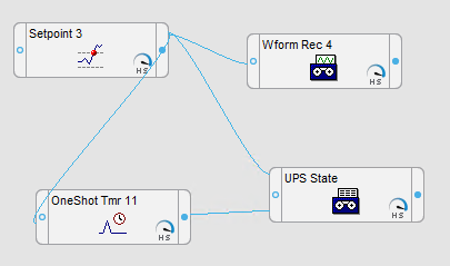
- Check that the waveform recorder input is linked to the V4 output of the Data Acquisition module.
- Save the framework.