Configuring the VIP Framework and Vista Diagrams for IEC
After the diagrams have been generated with the Insulation Monitoring Configuration Tool, configure the VIP framework and link it to the diagrams to display the alarm status from the Insulation Monitoring (IM) devices in the diagrams.
Creating a new VIP for the framework
You need to create a new VIP to set up the insulation monitoring VIP framework.
To create a new VIP:
- Open a Command Prompt window.
- Change the current folder to
...\Power Monitoring Expert\system\bin. - Type
vip -Service -NVIP.InsulationMonitoring_Alarmingon the command line.This creates a VIP service with the name VIP.InsulationMonitoring_Alarming.
- Open the Windows Services panel.
- Start the newly created VIP service.
Configuring the VIP framework
The VIP framework aggregates the alarm status for the different areas and group levels. The framework logic combines the different statuses using an OR condition, which means the summary status shows an alarm if one or more of the inputs are in an alarm state. The alarm summaries are then displayed in the Vista diagrams
To configure the VIP framework:
- Open Designer.
- Open the VIP.InsulationMonitoring_Alarming.
- Paste the framework
Insulation Monitoring Alarming Status for IEC.fwnin...\config\fmwk\InsulationMonitoringinto the VIP.The framework contains two groups with four areas each. This is meant to be a starting point. Add or remove areas, or entire groups to meet your needs. Here is an example of the default framework:
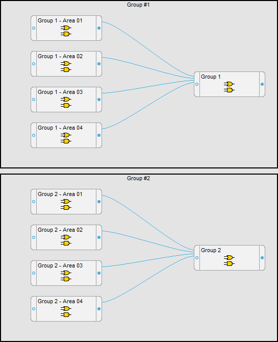
- Link the Alarm Status > Insulation Status Alarm, Electrical Status Alarm, and Wiring Connection Lost registers from the IMs to the Area AND/OR modules.
- Save the framework changes.
Finalizing the Vista Diagrams
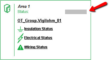
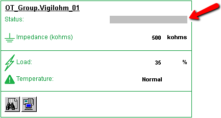
After the VIP framework is configured, open the diagrams in Vista and link the alarm status objects to the correct modules in the VIP framework, as shown below. The colors shown on the status objects are:
- Green - Normal. The Impedance measurement is below the limit.
- Red - Alarm. The Impedance measurement exceeds the limit.
- Gray - Unlinked. The object has not been connected to an alarm status register.
See Using the diagrams for alarm status display examples.
Group Level Diagrams
In the top-level Facility Summary diagram, link the alarm status object to the AND/OR module output for the Group level Status in the VIP framework.

In the example above, you would link the status object to the output of the Group 1 AND/OR module in the VIP.
Area Diagrams
Link the area status objects in the diagram to the corresponding Area AND/OR module outputs in the VIP framework.
Area Details Diagrams
Link the area details status objects in the diagram to the corresponding Area AND/OR module outputs in the VIP framework.
Opening diagrams in Power Monitoring Expert
After you have configured the diagrams, open them in Diagrams or Vista. Confirm that all monitoring devices are communicating as expected. Verify that all status objects in the diagrams are displayed correctly. Fix any unlinked or incorrectly linked objects.