Disable unused Power Quality Indicators
When a Power Quality Indicator has no supported device to feed it the required data, disable it by using the procedures in the following sections. See Supported Devices for Power Quality Performance monitoring for meter support information.
Disable Flicker, Frequency, Harmonics or Unbalance Indicators
Use the following procedure to disable the Flicker, Frequency, Harmonics, and Unbalance indicators. Flicker is used specifically in this example, but the procedure is the same for the other items.
You can also use the following procedure to disable Overvoltage and Undervoltage. However, note that it will disable both simultaneously. If only one needs to be disabled, use the procedure in the next section.
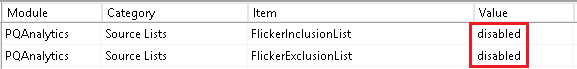
- To prevent Power Quality Performance from requesting Flicker values, add a string “disabled” to the FlickerInclusionList & FlickerExclusionList (no double quotes needed). See Change device inclusion and exclusion for the analysis for detail steps.
- To prevent the Power Quality Performance indicator diagrams from displaying status:
- Edit the VIP.PQADVISOR in Designer.
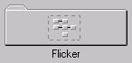
- Open the Flicker folder.
- Add a new Ext Bool Module.

- Link the switch output register of the new module to the Enable input register on the 4 XML import modules used for Flicker.
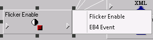
- Right click on the newly created Ext Bool Module
- Change the Module Label and the switch Output Register Label to “Flicker Enable”
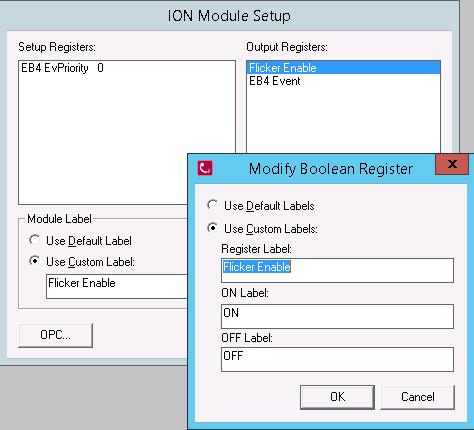
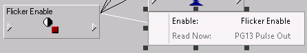
- Select the outputs for the Flicker Enable module and select “Flicker Enable”
- Select the input of the 24hr Flicker Count Import XML module and select “Flicker Enable”
- Repeat the previous step for the following:
7d Flicker Count Import XML module
30d Flicker Count Import XML module
1y Flicker Count Import XML module
- The result will look like this:
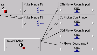
- Save the VIP and close Designer.
Since the Ext Boolean has a default value of “false”, the Flicker Count Import modules are disabled upon saving the VIP.
- Check the Power Quality Performance Indicator Diagram.
The Flicker icon should be grey.
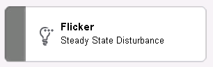
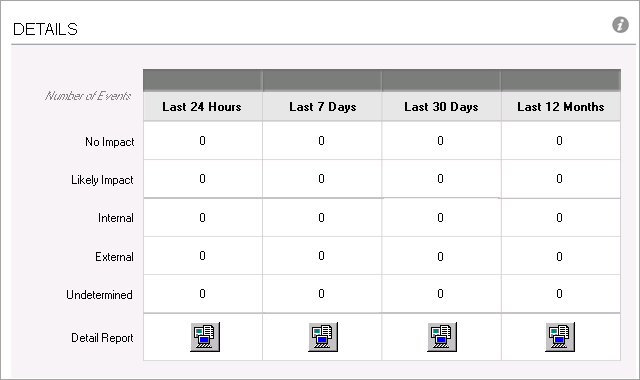
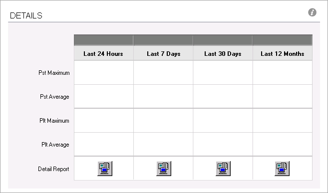
The details should be blank:
Disable Sag, Swell, Interruptions, Transient, or Unbalance Indicators
Use the following procedure to disable the Sag, Swell, Interruptions, and Transient indicators, if the devices being used in the installation do not support them. Transients are used specifically in this example, but the procedure is the same for the other items.
You can also use the following procedure to disable either Overvoltage or Undervoltage, if only one needs to be disabled. If both need to be disabled simultaneously, then use the procedure in the previous section.
- To Power Quality Performance from requesting Transient values, add the string “disabled” (without the quotes) to the TransientInclusionList and TransientExclusionList. See Change device inclusion and exclusion for the analysis for detailed steps.
- To prevent the Power Quality Performance indicator diagrams from displaying Transient status:
- Edit the VIP.PQADVISOR in Designer.
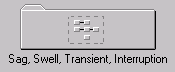
- Open the Sag, Swell Transient, Interruption folder.
- Right click on the 12m Event Ind Extrap module.
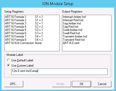
- Double click on Formula 7 and add “S5 + “ to the beginning of the string. This will cause the output of the equation to be NA because S5 is unassigned and therefore equivalent to NA. If transients need to be added back to the system (e.g. a new meter which supports transients is purchased for the site), then it is easy to remove the string “S5 +” from the setup register string

- Repeat step d for Formula 8
- Repeat steps c, d, and e for:
24h Event Ind Extrap module
7d Event Ind Extrap module
30d Event Ind Extrap module
- Save the VIP and close Designer.
- Check the Power Quality Performance Indicator Diagram. The Transient Voltage icon should be grey.

The DETAILS page should display zeros: