Generator system redundancy types
You can create a generator system to achieve power redundancy for IT equipment loads in different ways, depending on how the generators are grouped together and how they are connected to the equipment power supplies. This configuration tool supports several industry standard configurations.
The generator system supports the following redundancy design types:
Before generator-related reports can be produced you need to define a generator system in the Generator Power Configuration Utility.
N Type
The N system configuration is for one or more generators that work together to supply power to the IT load, when the utility or utilities’ power is unavailable. There is no redundancy. The intention is to size the generator system to match the peak IT load on the utility power.
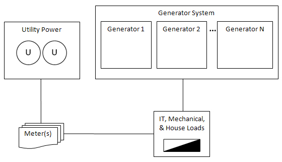
N+1 Type
The N+1 system configuration is for one or more generators that work together to supply power to the IT load. There is simple generator redundancy in that one of the generators can stop functioning or be taken off-line, if the utility power is interrupted. The load is spread among all generators, but the peak load is such that if one generator stops working, the others will be able to assume its load. Another way to look at it is, N generators will be able to support the peak IT load. If the peak IT load is more than N can support, then system design redundancy will be lost.
For example, if three generators are connected to the IT loads, in an N+1 system, the peak utility load must not exceed the non-redundant capacity of two of the generators. If it does, the designed redundancy will be lost.

N+2 Type
The N+2 system configuration is for a group of generators that work together to supply power to a medium voltage substation and is then distributed to low voltage loads. There is simple generator redundancy in that any two of the generators can stop functioning or be taken off-line, if the utility power is interrupted. The load is spread among all generators, but the utility peak load is such that if two generators stop working, the others will be able to assume their load. Another way to look at it is, N generators will be able to support the peak utility load. If the peak utility load is more than N can support, then system design redundancy will be lost.
For example, if five generators are connected to the IT loads, in an N+2 system, the peak utility load must not exceed the non-redundant capacity of three of the generators. If it does, the designed redundancy will be lost.

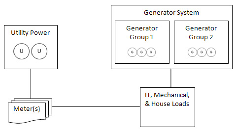
2N Type
The 2N system configuration is for two groups of generators that supply power to the IT loads. In a 2N system, an entire group of generators can stop functioning or be taken off-line and the equipment will still be supplied with power, if the utility power is interrupted. The load is spread among all generators, but the peak load is such that, if an entire group of generators stop working, the remaining generators will be able to assume the entire load. Another way to look at it is, N generators will be able to support the peak utility load. If the peak utility load is more than N can support, then system design redundancy will be lost.
In this example, there are two groups with three generators in each. In a 2N configuration, one group of generators can go offline and the system will still have the designed redundancy. Therefore, the value for N is three. So, the total peak utility load cannot exceed the derated nameplate of three of the generators.
2(N+1) Type
The 2(N+1) system configuration is for two groups of generators that supply power to the IT loads. In a 2(N+1) system, an entire group of generators plus one more generator from each of the remaining groups can stop functioning or be taken off-line, and the equipment will still be supplied with power, if the utility power is interrupted. The load is spread among all generators, but the peak load is such that if an entire group’s worth of generators goes offline, plus one more from each of the other groups stop working, the remaining generators will be able to assume the entire load. Another way to look at it is, N generators will be able to support the peak utility load. If the peak utility load is more than N can support, then system design redundancy will be lost.
In this example, there are two groups with five generators in each. In a 2(N+1) configuration, one group of generators can go offline, plus one more generator from the remaining group and the system will still have the designed redundancy. Therefore, the value for N is four. So, the total peak utility load cannot exceed the derated nameplate of four of the generators.

2(N+2) Type
The 2(N+2) system configuration is for two groups of generators that supply power to the IT loads. In a 2(N+2) system, an entire group of generators plus two more generators from each of the remaining groups can stop functioning or be taken off-line and the equipment will still be supplied with power, if the utility power is interrupted. The load is spread among all generators, but the peak load is such that if an entire group’s worth of generators goes offline, plus two more from each of the other groups goes offline, the remaining generators will be able to assume the entire load. Another way to look at it is, N generators will be able to support the peak utility load. If the peak utility load is more than N can support, then system design redundancy will be lost.
In this example, there are two groups with four generators in each. In a 2(N+2) configuration one group of generators can stop working, plus two more generators from the remaining group and the system will still have the designed redundancy. Therefore, the value for N is two. So, the total peak utility load cannot exceed the derated nameplate of two of the generators.
