Creating TGML graphic pop-ups
You can add a pop-up to a TGML graphic. When a user selects on a device in a TGML graphics page that has a configured pop-up, a pop-up is displayed. This topic lists the steps to add a pop-up to a device and includes an example to illustrate how to create a TGML graphic pop-up.
To create a TGML graphic pop-up:
- Open the Graphics Editor: Go to Start > Power Monitoring Expert > Graphics Editor.
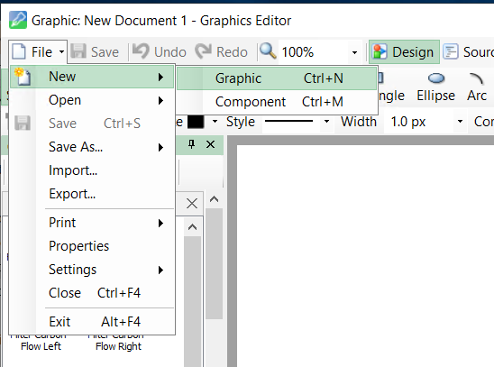
- Go to File > New > Graphic.
- Design the graphics based on the PME user requirement.
NOTE: Newly created TGML graphic pop-ups can be used for all the devices. When the user selects on a breaker in the PME Web Applications, the pop-up displays the same for all the components, but the values will be different based on the breaker.
Example
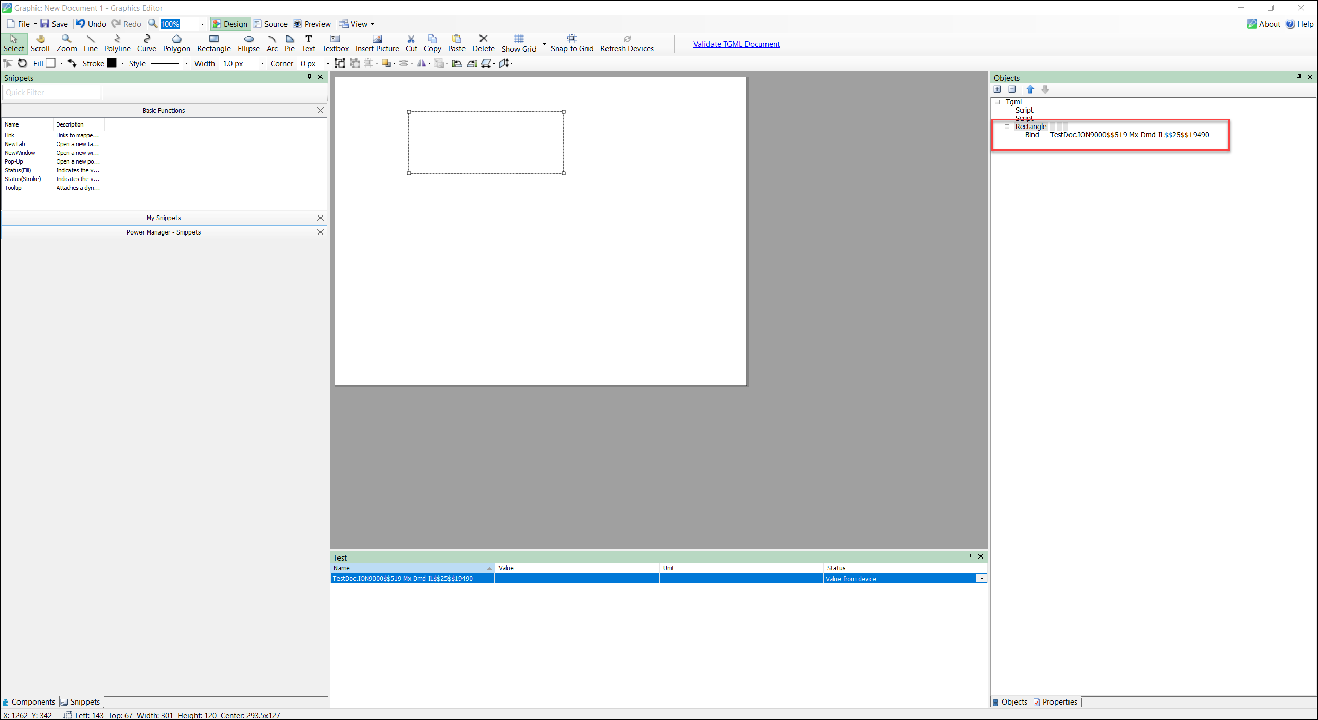
The following steps demonstrate how to create a rectangle box and bind it:
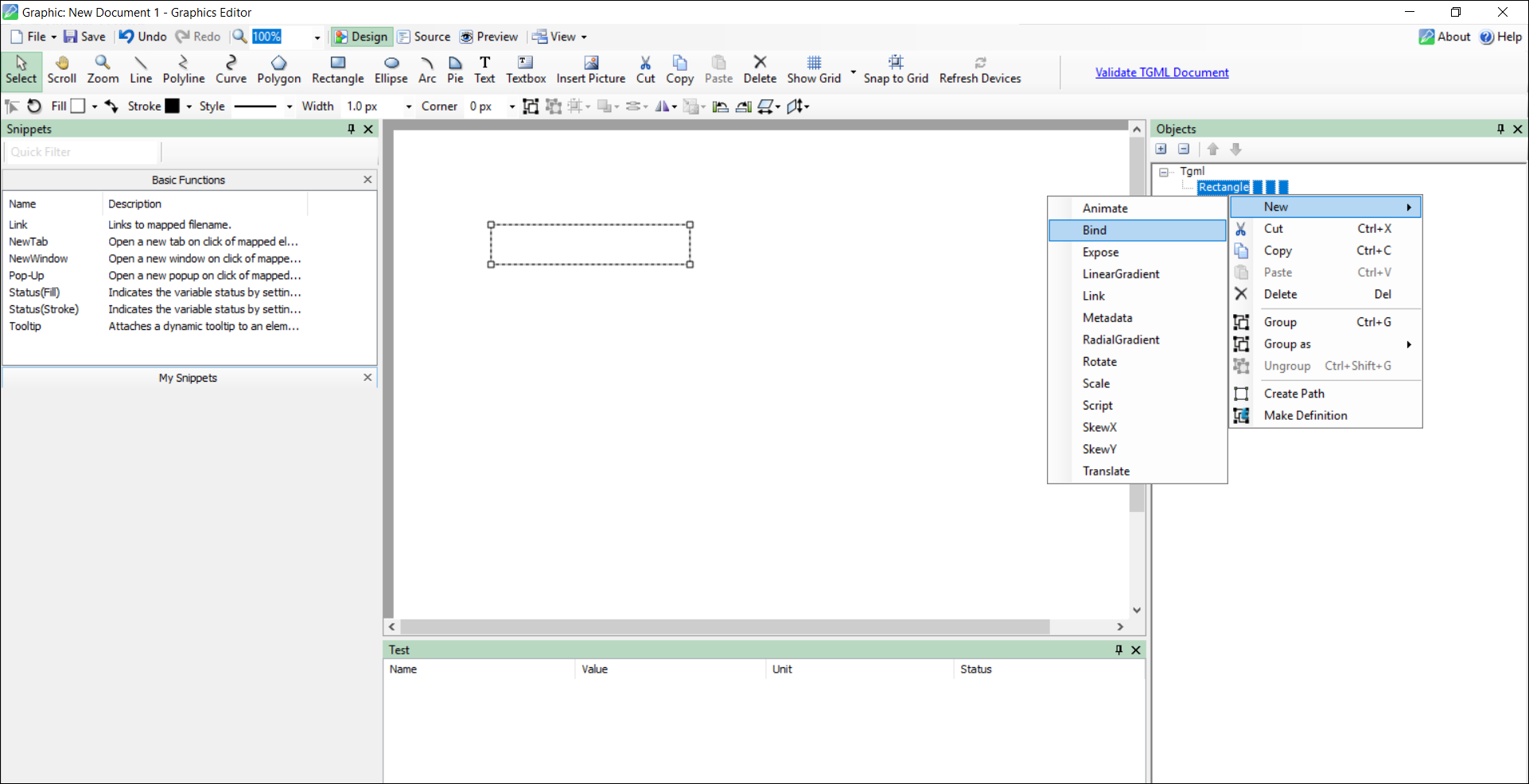
- From the top menu bar select Rectangle, draw on the workspace, and then select the Objects tab.
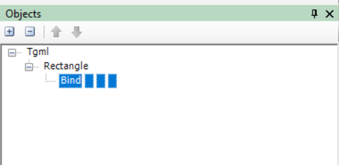
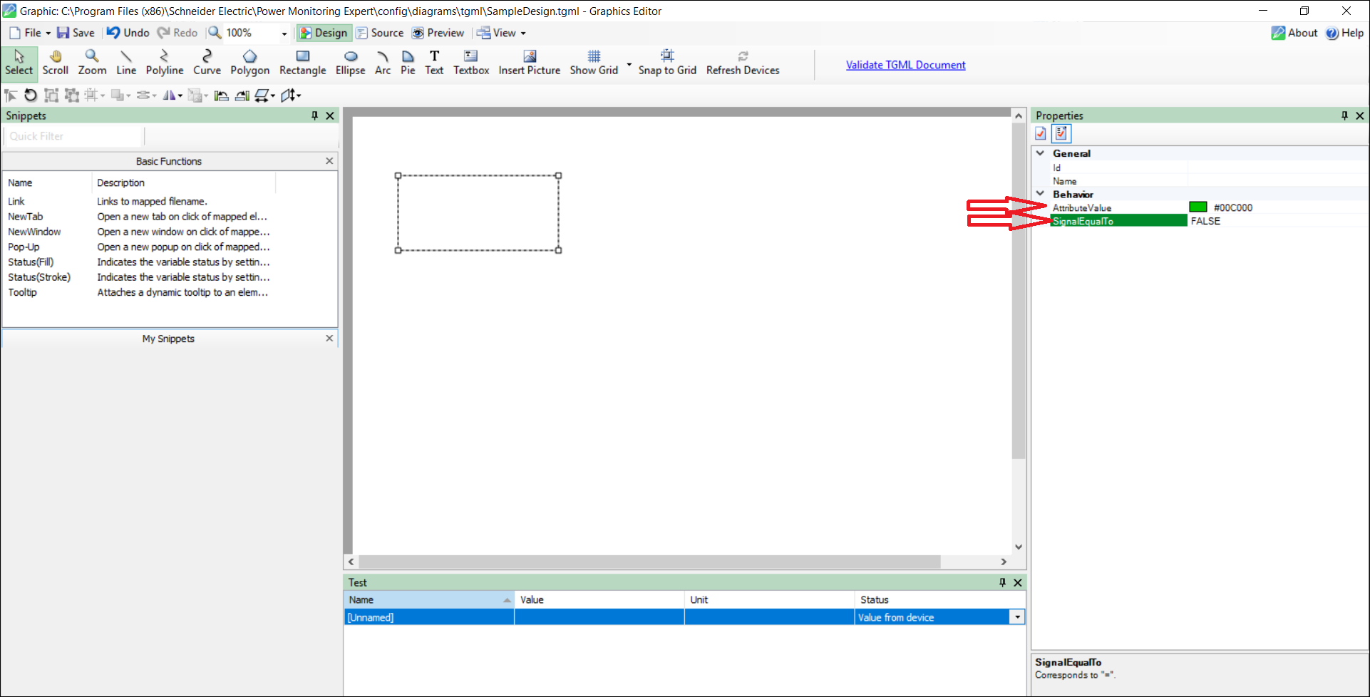
- Go to the TGML, right-click on Rectangle, select New, and then select Bind.
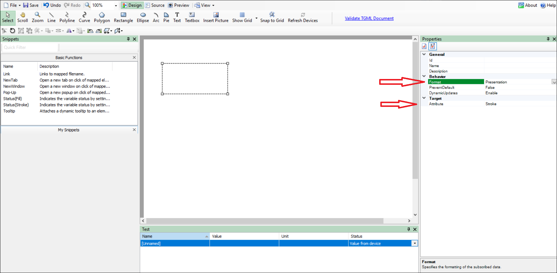
- Select Bind > press F2 or go to the Properties pane, and then set the value of Format to Presentation and Attribute to Stroke.
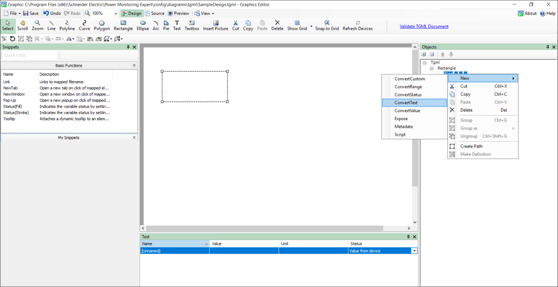
- Right-clickon Bind, select New, and then select ConvertText.
- Select ConvertText > press F2 or go to the Properties pane, select the appropriate stroke color, and then set SignalEqualTo to
FALSE. -
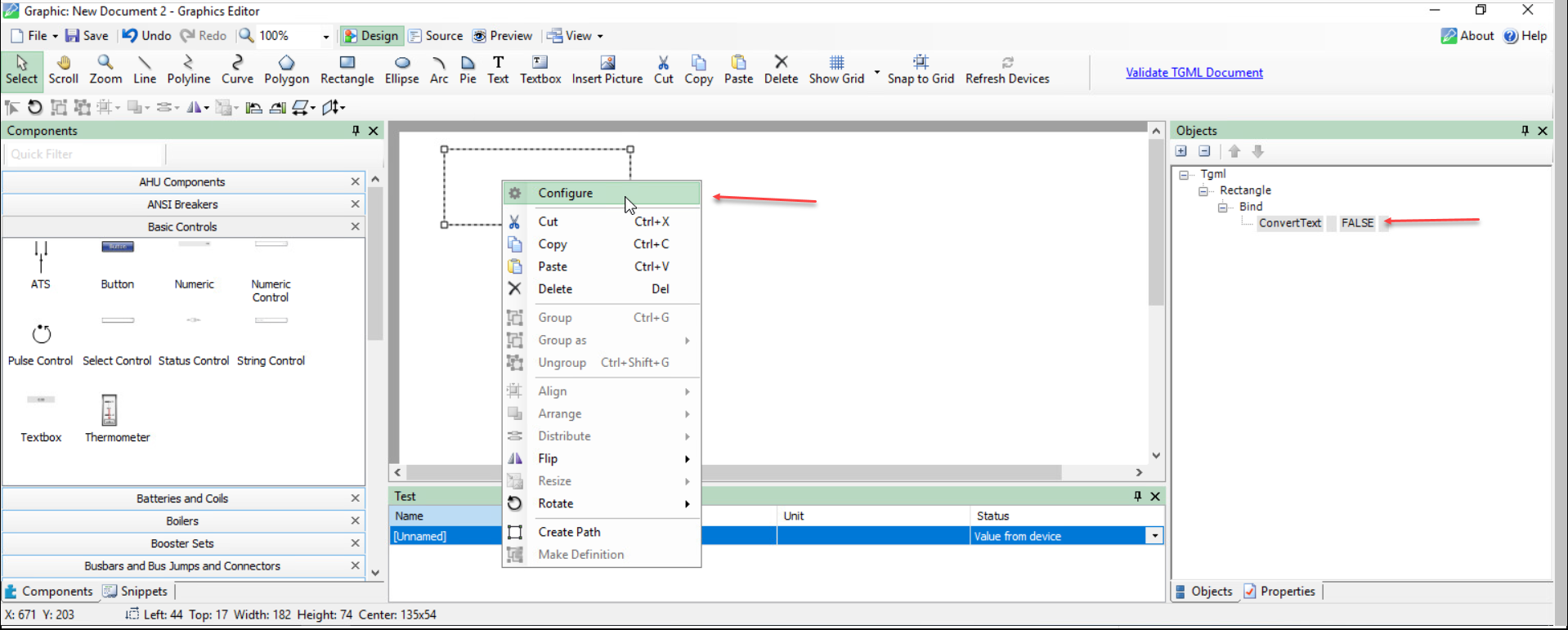
Right-click the component and select Configure.
- Select the configuration for the component:
- Select the Sources.
- Select the Managers.
- Select the Modules.
- Select the Registers.
- Select Apply after you make the changes to the bind.
- Save the TGML file.
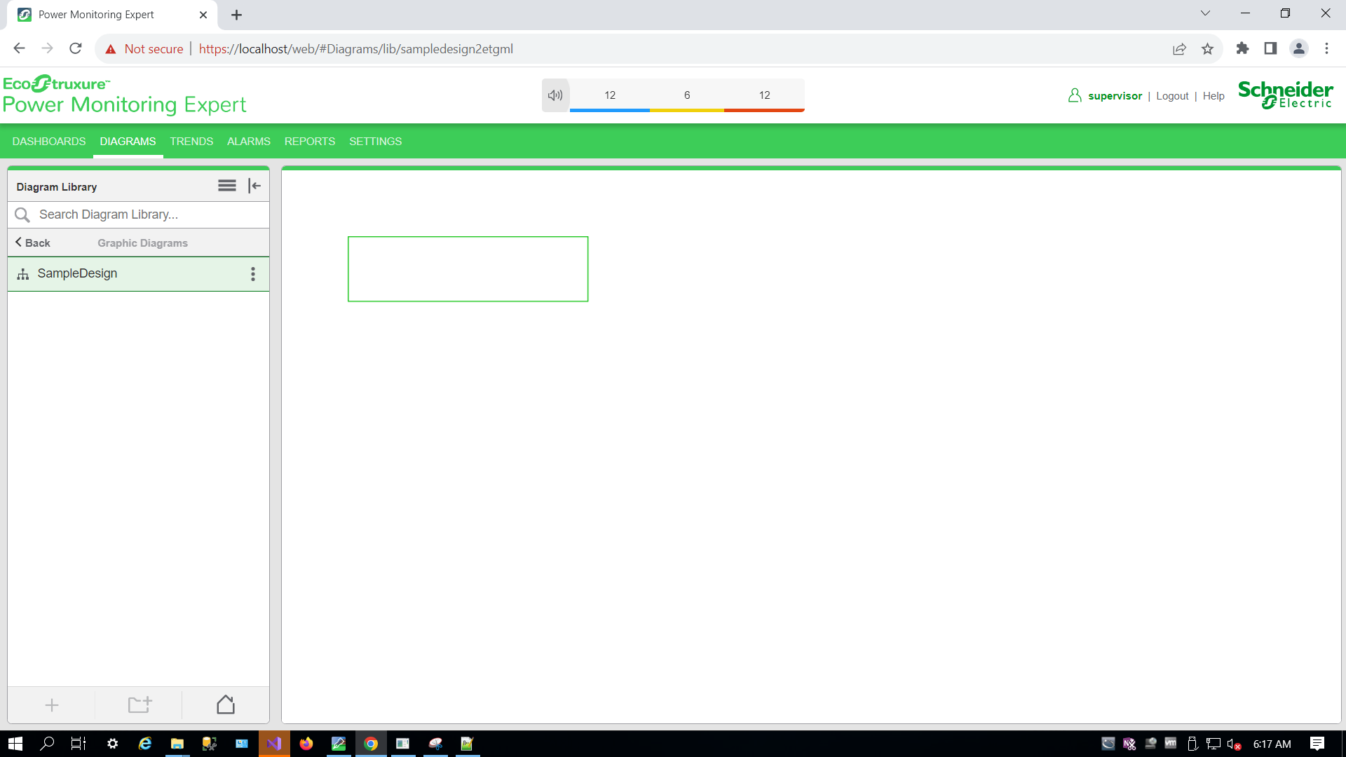
- Log in to the PME Web Applications.
- Select on the created TGML file in the Diagram Library menu.
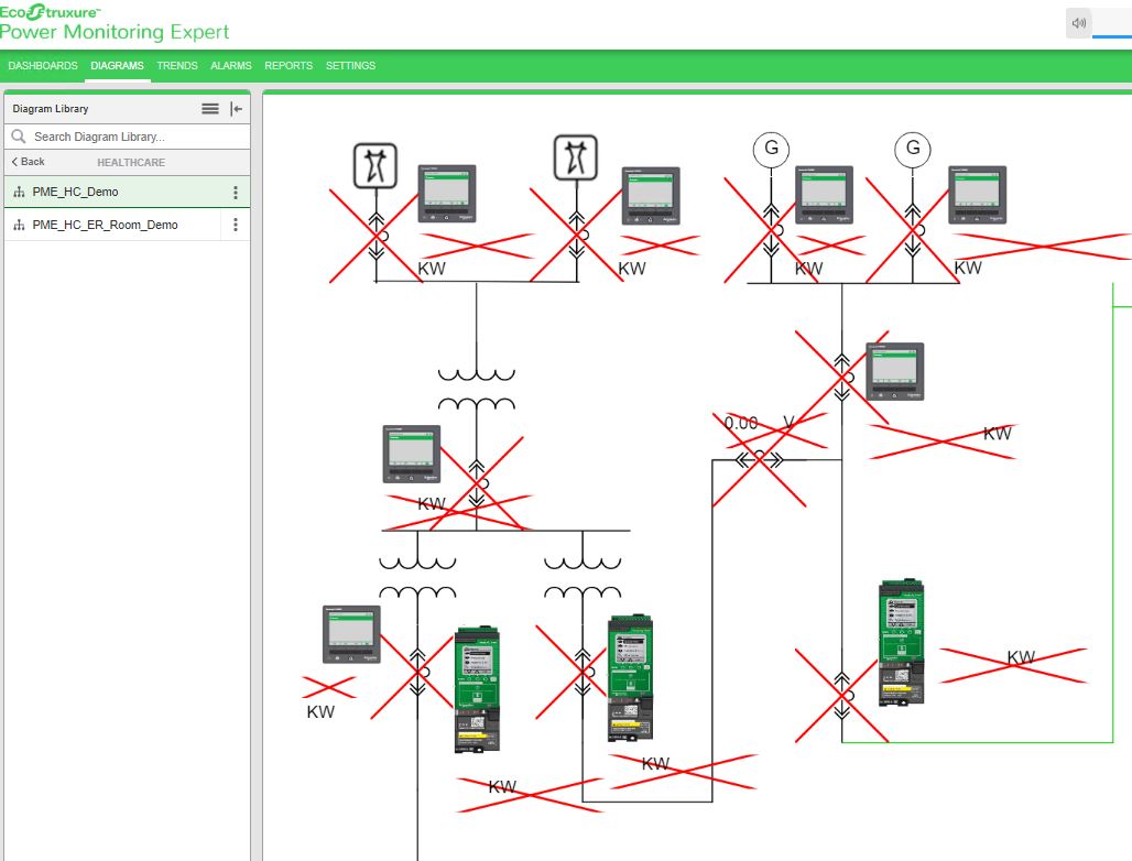
The following screen is displayed:
NOTE:
To configure other signal values, repeat step 5. For example: TRUE or DISCONNECTED.
NOTE: If the bind name is used without component, rename the bind to: Device Name$$Measurement Name$$Handle Number. Device Name$$Measurement Name.
Rendering error conditions in pop-up using presentation value
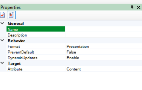
In the bind properties, the Presentation values are Format = Presentation, Attribute = Content:
The following table explains the error rendering with the respective place holder that appears in the output Pop-Up as shown in the previous image:
| Comm Loss |
|
| NA Value | -INF |
| Quality is good | Show Value returned by API |
| PME not running | Default Comm Loss |
| Unknown |
|
For example, when PME is shut down, the default comm loss is shown below: