NOTE: This report is part of the Backup Power Module. This module requires a separate license.
Summary
The Generator Test EPSS Report shows load measurements and the sequence of events for generator test runs. You can configure it to meet the requirements of an Emergency Power Supply System (EPSS) test, including Automatic Transfer Switches (ATS). Use this report to assess the performance of your backup generation systems during test runs. You can also use this report to evaluate pass/fail criteria for EPSS testing.
NOTE: Emergency Power Supply System (EPSS) is a North American term used in the healthcare segment. It describes an arrangement of generators and automatic transfer switches, designed to provide backup power in case of a utility power interruption.
Prerequisites
- The Backup Power Module must be configured.
- The measurement data must be available as historical data logs in the database.
Report inputs:
Type a title for the report in the text box.
Type a name for the company in the text box.
Type a name for the technician in the text box.
Select the group for which the report is intended.
(Optional) Define the sources to exclude from the report:
- In the Sources Included area, select sources to exclude and then click > to move those sources to the Sources Excluded area.
- To move all of the sources into the Sources Excluded area, click >>.
- Click OK to save the sources and return to the report template.
The devices in the group appear in the Sources section of the generated report. Excluded devices appear as grayed-out entries.
Click Use Run History to select the most recent run, or select other specific runs that are stored in history, and then do the following:
- Click Refresh Run History to populate the Runs list with the latest run records.
- In the Runs list, select
Most recent runor the specific run record. The date and reason for the run appear below the dropdown list.If you select
Most recent runand define excluded sources, the exclusions are ignored when you generate the report.
Select this if you want to select the runs according to a date range and run reason, and then do the following:
- Select the Reporting Period date range for the runs to include in the report.
- Select the Run Reason for the runs to include in the report.
The devices in the group will appear in the Sources section of the report. Devices that you excluded from the report will be gray-shaded.
NOTE: Transfer Switches and Active Transfer Switches (ATS) are not typically part of a data center solution. If your system does not include transfer switches, you do not need to configure them.
Complete the following steps to configure the Automatic Transfer Switch Summary section of the Generator Test Report:
- Click ATS Summary.
- Click Include ATS Summary to include the Automatic Transfer Switch Summary section in the report. The remaining options in the screen are enabled. Alternatively, clear this check box to exclude the Automatic Transfer Switch Summary section from the report.
- Click Include Pass/Fail Indicator to include both the Required Transfer Time and Test Result fields.. The Test Results shows the pass/fail grade. Alternatively, clear this check box to exclude the results from the report.
- Lead ATS - Select the ATS device that you want to use as the lead ATS in reporting the transfer time. The lead ATS is the ATS upon which the pass/fail grade is based.
You can choose the
Auto Select Lead ATSoption if you want the system to automatically select the lead ATS. The ATS device that is first to enter test mode becomes the lead ATS. If multiple ATS devices enter test mode at the same time, or if none of the devices enter test mode, the system selects the ATS based on alphabetical order. - Click OK to save your changes and return to the report template.
Complete the following steps to configure the Events Summary section of the Generator Test Report:
- Click Events Summary.
- Click Include Events Summary to include the Events Summary section in the report. The remaining options in the screen are enabled. Alternatively, clear this check box to exclude the Events Summary section from the report.
- Click Include Generator Events to include generator events in the report. Alternatively, clear this check box to exclude generator events from the report.
- Click Include ATS Events to include ATS events in the report. Alternatively, clear this check box to exclude ATS events from the report.
- Click OK to save your changes and return to the report template.
Complete the following steps to configure the Generator Summary section of the Generator Test Report. If the EPSS group has multiple generators, these settings will be applied to all generators in the group.
NOTE: If you selected Load Bank when you configured the evaluation method for a generator in the group, the Generator Load Summary section of the EPSS Test Report shows the details of the selected stages of the load bank test. The stages are represented on the graph.
- Click Generator Summary.
- Click Include Generator Summary to include the Generator Summary section in the report. The remaining options in the screen are enabled. Alternatively, clear this check box to exclude the Generator Summary section from the report.
-
Click Include Pass/Fail Indicator for Time to EPS Available to include the pass/fail grade for emergency power source availability. Alternatively, clear this check box to exclude the pass/fail grade.
- Click Include Pass/Fail Indicator for Generator Evaluation to include both the pass/fail grade and the evaluation method used to evaluate each generator. The pass/fail grade is based on both the run duration and the minimum specified percentage of the prime nameplate rating. Alternatively, clear this check box to exclude the pass/fail grade and the evaluation method from the report.
- Select the Load Details options to specify the electrical data in the report:
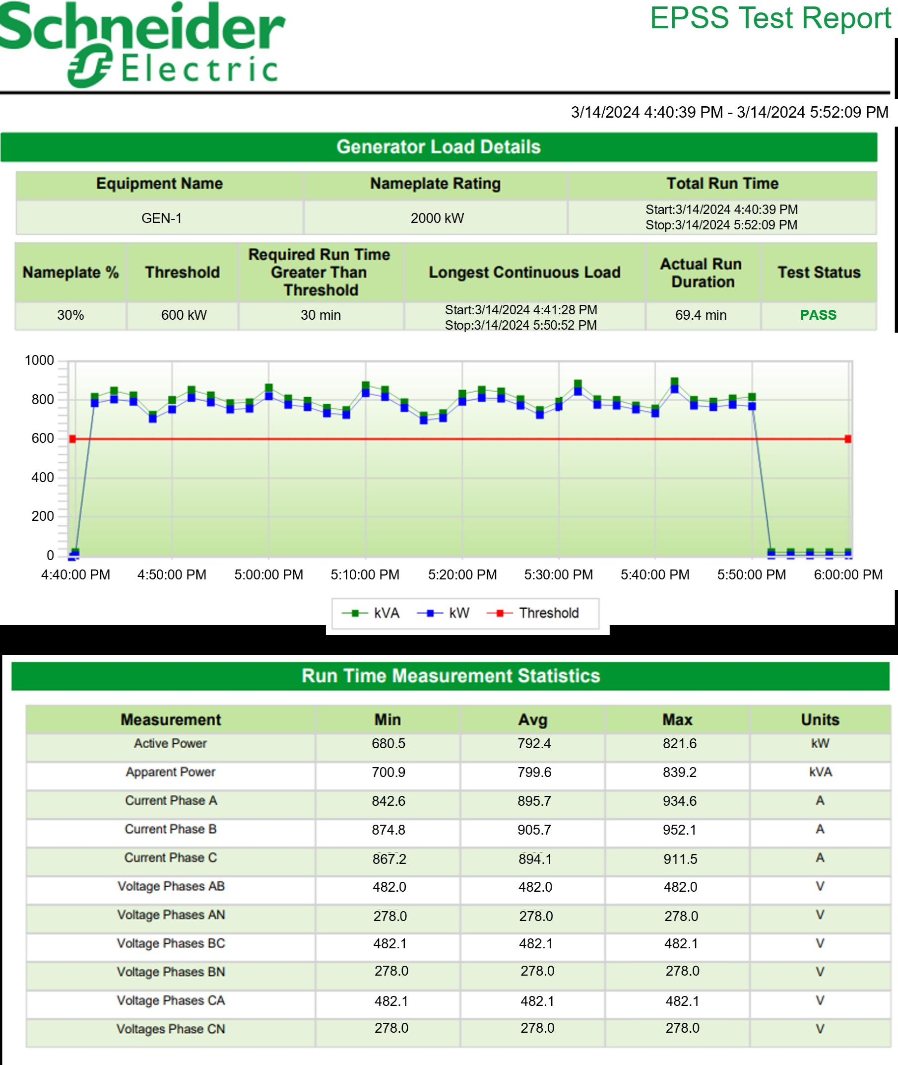
- Include Chart: Select this check box to include a generator chart showing kW Load, kVA Load, and the threshold for the minimum acceptable power load based on the specified load percentage for the run duration.
- Include Statistics Table: Select this check box to include a table showing minimum, average, and maximum electrical readings for the longest continuous load at (or above) the specified load percentage. The electrical readings measured are: kW, kVA, Ia, Ib, Ic, In, Vab, Van, Vbc, Vbn, Vca, Vcn.
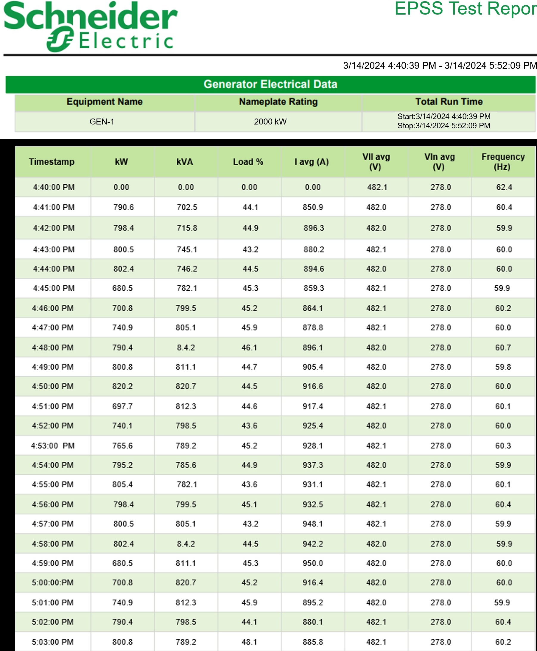
- Include Data Table: Select this check box to include a table showing the generator electrical details. The data is organized by time intervals and displays the readings for kW, kVA, load (the percentage of maximum load identified on the generator nameplate), Power Factor (PF), I avg, VLL avg, VLN avg, and Frequency.
- Select the Engine Temperature Details options to specify the engine temperature data in the report:
- Include Chart: Select this check box to include a chart showing the engine temperature for the run duration, and a horizontal line identifying the minimum temperature required for the run duration.
- Include Statistics Table: Select this check box to include a table showing Minimum, Average, and Maximum engine temperature readings for the longest continuous engine temperature equal to or above the minimum acceptable engine temperature.
- Include Data Table: Select this check box to include a table showing the Longest Continuous ET (Engine Temperature) time period, the Minimum ET, Required Run Duration (Min), and Actual Run Duration.
NOTE: The configuration tool does not convert the engine temperature values from one temperature type to another.
- Select the Exhaust Gas Temperature Details options to specify the exhaust gas temperature data in the report:
- Include Chart: Select this check box to include a chart showing the exhaust gas temperature for the run duration, and a horizontal line identifying the minimum temperature required for the run duration.
- Include Statistics Table: Select this check box to include a table showing Minimum, Average, and Maximum exhaust gas temperature readings for the longest continuous engine temperature equal to or above the minimum acceptable exhaust temperature.
- Include Data Table: Select this check box to include a table showing the Longest Continuous EGT (Exhaust Gas Temperature) time period, the Minimum EGT, Required Run Duration (Min), and Actual Run Duration.
- Under Engine Data, click Include Data Table to include engine details in the report. Details for each generator include:
- Generator name
- Generator start and stop times by date
- A label to indicate whether the data was collected automatically or manually.
- A table of measurements; such as battery voltage and coolant temperature. Each measurement includes a timestamp and the corresponding values.
- Click OK to save your changes and return to the report template.
Use this field to add comments that will appear at the bottom of the generated report.
Click Yes to include data notifications in the report. If there are none, the section is not included. Click No to exclude this section.
Example:
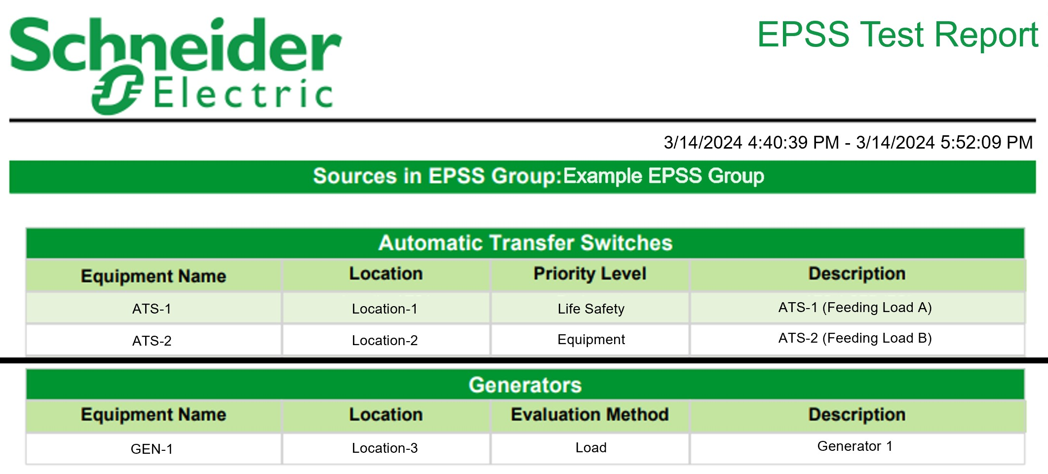
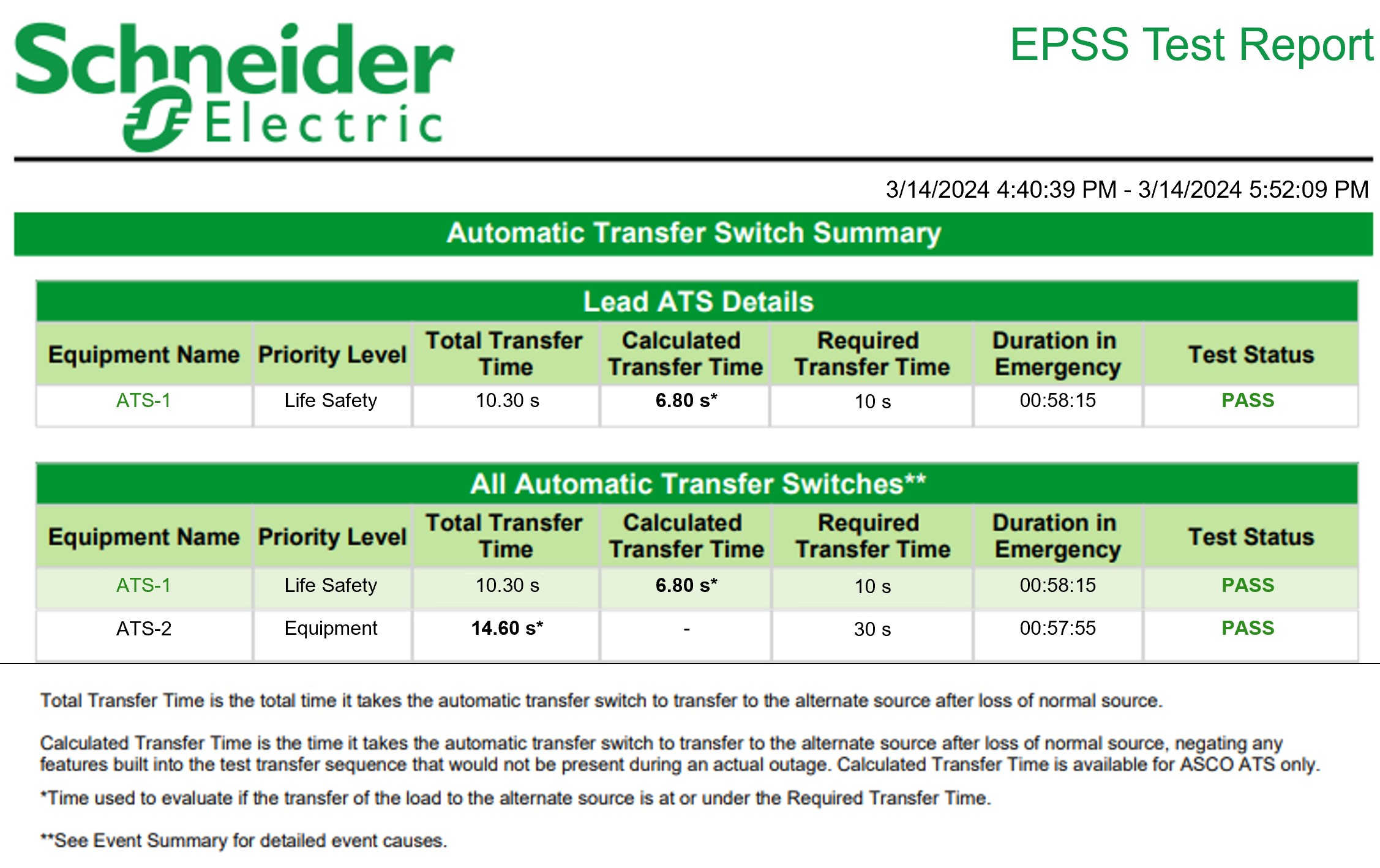
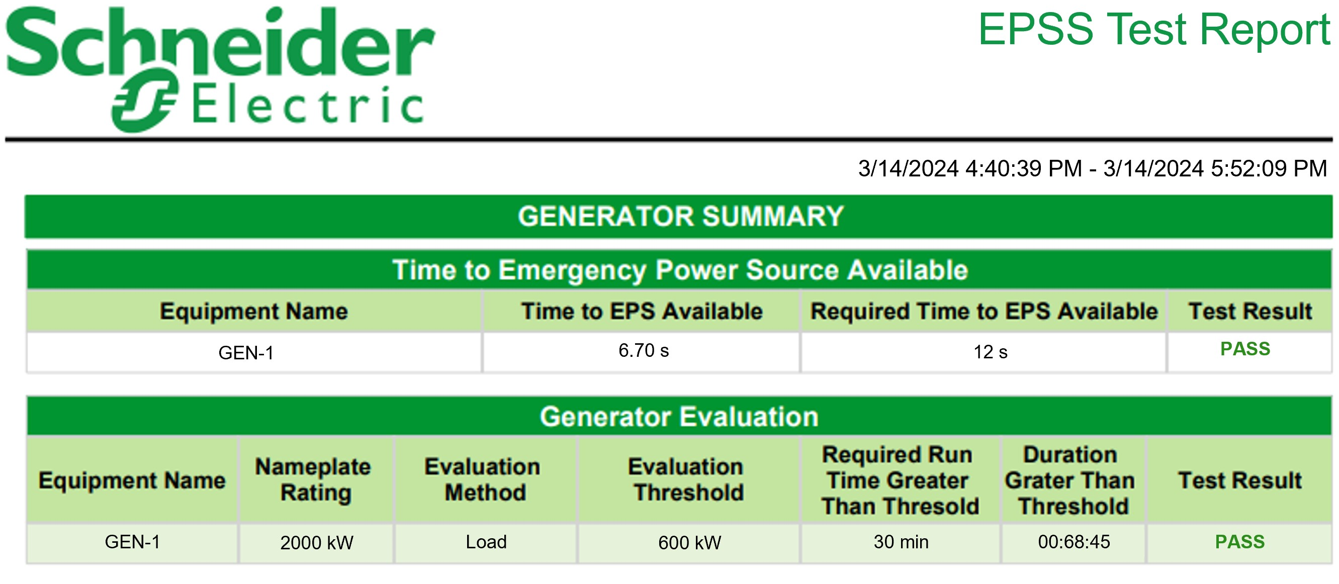
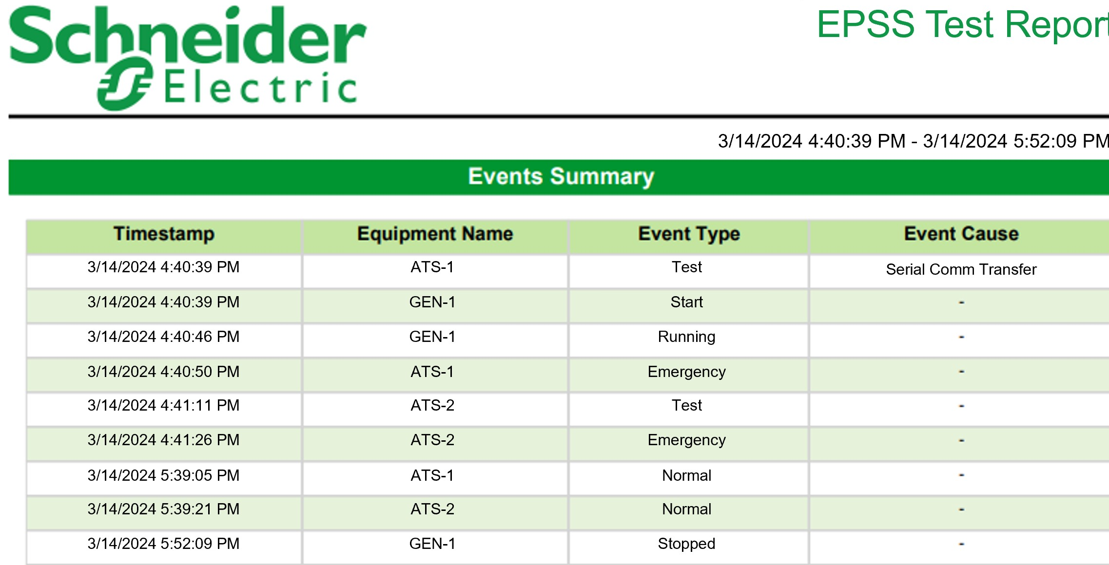
NOTE: This example only shows selected content from the report, it does not show the entire report.