NOTE: This report is part of the Backup Power Module. This module requires a separate license.
Summary
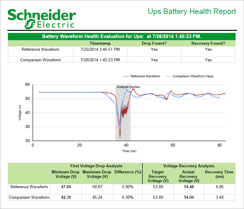
The UPS Battery Health Report compares the UPS battery voltage, during test conditions, with a reference voltage signature. Use this report to check the UPS battery performance and to plan preventive maintenance.
For information on the terms and calculations used in this report, see UPS Battery Health Report calculations.
Prerequisites
- The Backup Power Module must be configured.
- The measurement data must be available as historical data logs in the database.
Report inputs:
Type a title for the report in the text box.
- Click Select Source, choose a source from the list, and then click OK.
- Click Select Reference Waveform, select the check box next to one or more comparison waveforms, and then click OK.
- Define the comparison waveforms using one of the following:
- Click Enter the number of comparison waveforms and enter a value in the field.
By default, the report looks for the five most recent waveforms that have been captured for the source to be compared against the reference waveform. Use this mode for reports that are to be delivered using a report subscription.
- Click Select the comparison waveforms, then click Select Comparison Waveforms, select the check box next to the waveforms you choose, and then click OK.
This mode allows you to select specific comparison waveforms. It is not recommended to use this mode with a report subscription.
- Click Enter the number of comparison waveforms and enter a value in the field.
Enter a percentage value from 1.00 to 100.00. This input value represents the percentage that is used by the algorithm to detect the first voltage drop in the reference and comparison waveforms.
Enter a value for this sample size. This input represents the number of waveform samples (or points) - from 2 to a total number of waveform samples (for example, 1024, 2048, and so forth) - used by the algorithm in the detection of the waveform voltage drop for the reference and comparison waveforms.
Enter the multiplier value from 0.01 to 1.00. This value is used by the algorithm to determine the waveform recovery voltage value and time (relative to the waveform voltage drop) for both reference and comparison waveforms.
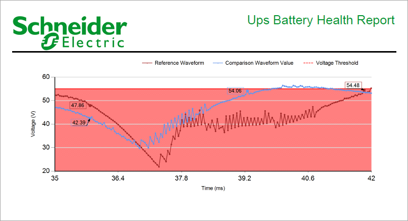
Enter voltage threshold value. This input represents a nominal voltage that is used by the report to display a voltage threshold area below the reference waveform voltage drop.
Click Yes to include data notifications in the report. If there are none, the section is not included. Click No to exclude this section.
Example:


NOTE: This example only shows selected content from the report, it does not show the entire report.