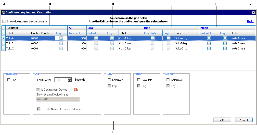
Configuring Logging and Calculation User Interface
Use the Configure Logging and Calculation utility to:
- Enable register logging, including setting log frequency.
- Enable low (minimum), high (maximum) and mean (average) calculations and logging.
- Configure stale data settings.
- Append downstream device information to labels.
NOTE: Only numeric output registers can be calculated and logged. All other types of registers (for example, enumerated) do not appear on the Configure Logging and Calculation screen.
Screen overview

|
||||||||||||||||||||||||
|
||||||||||||||||||||||||
All the register information from the device type in the Device Type Editor is pre-populated in this table when you open the application.
Show downstream device columns: Select this to show all the columns for selecting and setting the downstream device properties for registers.
Register area: Use this area to individually configure registers.
Low area: Use this area to enable calculation and set logging of low values.
High area: Use this area to enable calculation and set logging of high values.
Mean area: Use this area to enable calculation and set logging of mean values.
Global register edit area: Use the bottom half of the screen to edit individual registers or multiple registers, after selecting them in the list.
Help link: Click this link to open the Device Type Editor online help.
Stale data link (All): Click this link to open the Configure Stale Data Settings dialog.
Configuring register logging
To edit registers on an individual basis, select the row of the register and edit the cells in the row or use the editing tools in the Global area.
To edit more than one register, select the rows you want to configure similarly and use the editing tools in the Global area.
Log: Select to enable logging of the register.
Interval: This value determines the logging frequency for the register. Note that this value also controls the reset interval for the min, max and averaging modules, even if these calculations are not being logged. The valid range is 1 to 4,000,000 seconds.
Configuring Low, High and Mean Calculation and Logging
To edit the suffix used for Low, High and Mean, click on the applicable link. For example, if you change the suffix to Maximum, VoltsA High becomes VoltsA Maximum.
Low
Select Calculate to enable calculation of low (minimum) values for this register. Select Log to enable logging of this value. Note how the label is appended to reflect that this is the low value.
High
Select Calculate to enable calculation of high (maximum) values for this register. Select Log to enable logging of this value. Note how the label is appended to reflect that this is the high value.
Mean
Select Calculate to enable calculation of mean (average) values for this register. Select Log to enable logging of this value. Note how the label is appended to reflect that this is the mean value.
Configuring Stale Data settings
The “staleness” of data is measured from time data was last read from a physical device until the current time.
Click the All (Stale Data) link to open the Configure Stale Data Settings dialog.
Mark data stale after: Enter the time you want to elapse before data from this register is marked stale in the data recorder. The valid range is 0 to 7200 seconds.
When data is stale: Select how you want stale data values logged. The setting “log an empty row” logs an empty row in the data recorder, while “use last known value” logs the last non-stale value in the data recorder until the end of the current interval.
NOTE: Stale data settings are global (they apply to all registers) for a device type.
Configuring downstream device functionality
You must select the Show downstream device columns check box in the Configure Logging and Calculation window before you can edit downstream device functionality.
Show downstream device columns: Select this check box to make the downstream device columns appear.
Is Downstream Device: Select this checkbox to indicate the register belongs to a downstream device.
Downstream Device Name: Enter the name of the downstream device in this field. The register label is appended with this name. For example, if the device name is Meter01, the register label becomes VoltsA@Meter01.
NOTE: Using this option without also using the Include Name of Device Instance option causes multiple devices to appear as a single device in your energy management system. Do not use this option on its own unless only a single instance of this device is present in your system.
Include Name of Device Instance: Select this check box to append the actual device instance name to the register label. The placeholder !!DeviceName!! is then added to the label — the name of the actual device instance gets inserted when it is created.
For example, if the device instance is named Device01:
VoltsA@!!DeviceName!!Meter01
is replaced with
VoltsA@Device01Meter01
This allows for the creation of unique names within Power Monitoring Expert, as well as enabling each device instance to appear in the product as multiple virtual devices.
For more information on downstream devices and naming conventions,
Saving and exiting
To exit the Configure Logging and Calculation screen:
- Click OK to save your settings.
- Click Cancel to exit without saving.
You are returned to the main Device Type Editor console screen.