PAC configuration
The PAC system configuration is the same for these three platforms.
Unity Pro
- In the tree pane, expand Project Settings > General > PLC embedded data and then under Property Label, click Data dictionary.
This allows any client (SCADA using OFS) to animate or modify all symbolized variables of the application embedded in the PLC’s memory.
- In the tree pane, expand Project Settings > General > Time and then set Time Stamping Mode to System:
Max events stored is used for adjusting the buffer size of the time stamping by the M580 CPU. The value is between 0 and 4000.
NOTE: Its minimum value = 4 * number of events configured (including SOE_UNCERTAIN). If this configured value is too small, Unity Pro will show a build error and indicate the minimum events number in the message window.
BMX ERT
The BMX ERT module is installed in the M580/M340 backplane or x80 drop using the device DDT mapping methodology:
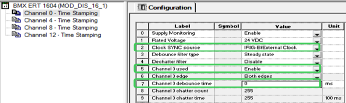
- Double-click on the BMX ERT 1604 T module to enter the Configuration window and then configure the following:
- Define the ‘Clock SYNC source’ for the ERT module.
- Enable or disable each of the 16 discrete channels in the field, ‘Channel x used,’ according to the application.
- Set the ‘debounce time’ of the enabled channel to 0ms, if you need to meet the requirement of a 1ms event resolution.
For example:
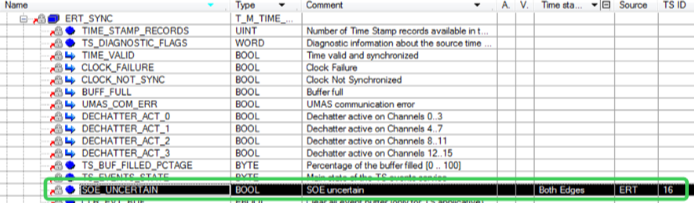
- Open the module’s ‘Device DDT’ tab and then click Goto detail. All the elements within this Device DDT are shown in the Data Editor.
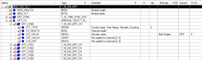
- The parameter, SOE_UNCERTAIN, is activated by default, and is time stamped by both edges.
x80 CRA
The x80 CRA module can be installed in the x80 remote I/O drops.
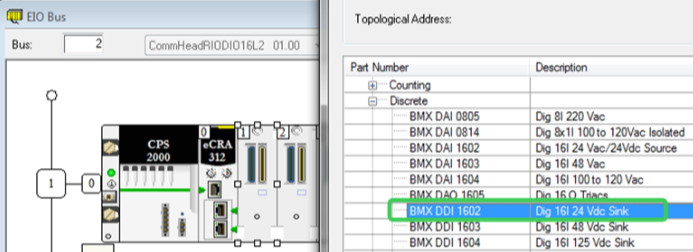
- The x80 CRA can time stamp the discrete I/O events detected by modules inserted in the remote I/O drop. Add a discrete I/O module in the x80 drop by double-clicking on an empty slot. Select a BMX DDI 1602. For example:
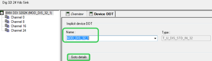
- Open the properties page of the discrete I/O module. Select the Device DDT tab, and click Goto details to open the Data Editor window. The ‘Name’ of the ‘Implicit device DDT’ can be modified as the application requires.
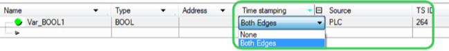
- Expand the elements under the implicit device DDT name of the BMX discrete I/O module. Expand the elements under ‘DIS_CH_IN’ of the input module, or ‘DIS_CH_OUT’ of the output module. Expand the elements under the required time stamping channel, and enable the channel by selecting the proper event in the ‘Time stamping’ cell.
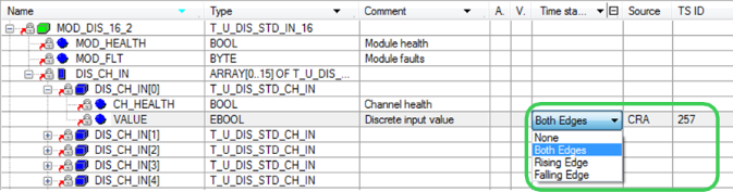
NOTE: For the M580, this attribute can be ‘None,’ ‘Both Edges,’ ‘Rising Edge,’ or ‘Falling Edge.’ For Quantum, however, the only options are ‘None’ or ‘Both Edges.’
- The parameter – SOE_UNCERTAIN – is already listed in the CRA drop’s device DDT, and the ‘Time stamping’ attribute has automatically been set to ‘Both Edges’ and assigned a TS ID.

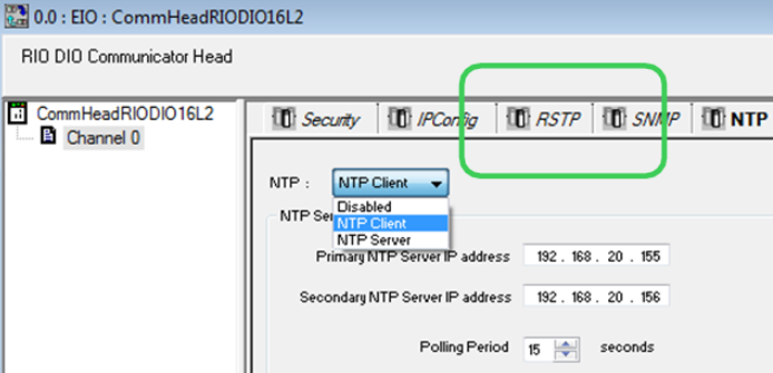
- Open the Quantum CRP or the M580 communication configuration window. Enable the NTP service to provide the time synchronization service for x80 CRAs. Configure the primary or secondary server’s IP and polling period. For example:
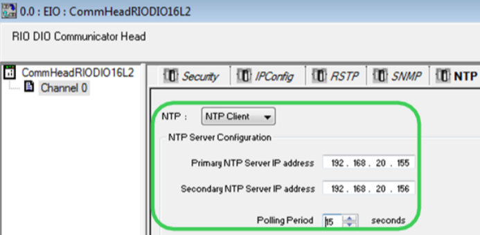
NOTE: It is recommended that the polling period be set to lower than 20s in order to get a time stamp resolution of 10ms between two events on different CRA modules.
For the M580, configure the CPU as either the NTP server or client. Both can provide time synchronization for the x80 CRAs.
- In the M580 platform, the x80 CRA’s buffer behavior settings can be adjusted in the ‘Time Stamping’ tag of its configuration window.
- On buffer full: Stop the recording or overwrite the oldest value when the event buffer is full.
- On power on: Erase the local buffer or do nothing when detecting a CPU powering on.
- On stop to run: Erase the local buffer or do nothing when detecting a PLC transitioning from stop to run.
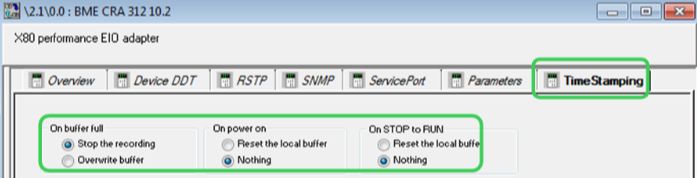
NOTE: While installed in Quantum remote I/O drops, the CRA’s time stamping buffer behaviors are set to the default value (as per the figure previous) and cannot be modified.
M580 CPU
This section presents the configuration steps of the time stamping by internal variable changes in the M580 program.
-
In the ‘Data Editor,’ select a BOOL type internal variable which can trigger a time stamping event; then select the trigger condition. Unity Pro will generate a TS ID.
NOTE: The internal buffer of the M580 CPU’s time stamped events will behave as follows: The CPU stops recording new events when the buffer is full.
- Manually create the SOE_UNCERTAIN variable for the M580 CPU, and locate this BOOL at %SW73.7. Enable its time stamping selection.

- In the M580, two kinds of time synchronization methods are allowed:
- External time source: The CPU is set as an NTP client and synchronizes its internal clock with an Ethernet NTP server, usually located on the control network.
- Internal time source: The CPU is set as an NTP server. Using its internal clock, the M580 CPU provides the time synchronization service for the other connected devices.
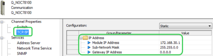
Quantum 140 NOC 78100
The Quantum Ethernet control module, 140 NOC 781 00, acts as the router between the x80 ERT or x80 CRA module installed in the device network and OFS installed in the control network.
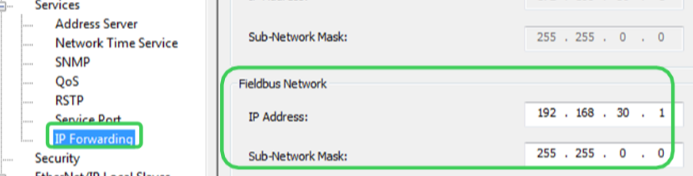
- In the Unity ‘DTM Browser,’ enable the ‘IP Forwarding’ service.
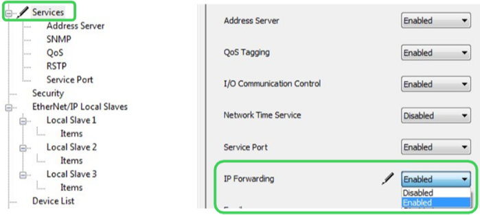
- Configure its IP address for the control network port (Eth port 3&4) on the ‘TCP/IP’ page.
Configure its IP address for the device network port (Eth port 2) on the ‘IP Forwarding’ page.