Power Operation configuration
The time stamped variable tags need to be configured in Power Operation Studio to represent the corresponding time stamped variables in the PAC.
- In Power Operation Studio, create a new I/O device for the system time stamping. In Topology > I/O Devices, click Express Wizard and then configure the settings according to the device’s requirement:
- Select the SCADA project that you want to create the device in.
- Click Use an existing I/O Server, select the existing server, and then click Next.
- Click Create a new I/O Device, enter an alias for the device, and then click Next.
- Click External I/O Device, and then click Next.
- Select the communication method, then click Next.
- In Address, enter the I/O device alias name. This value must be identical to the alias name you created in step c. Click Next.
- Link the device to an external tag database. Click Link I/O Device to an external tag database, browse to the database, and then enter the connection information. For example:
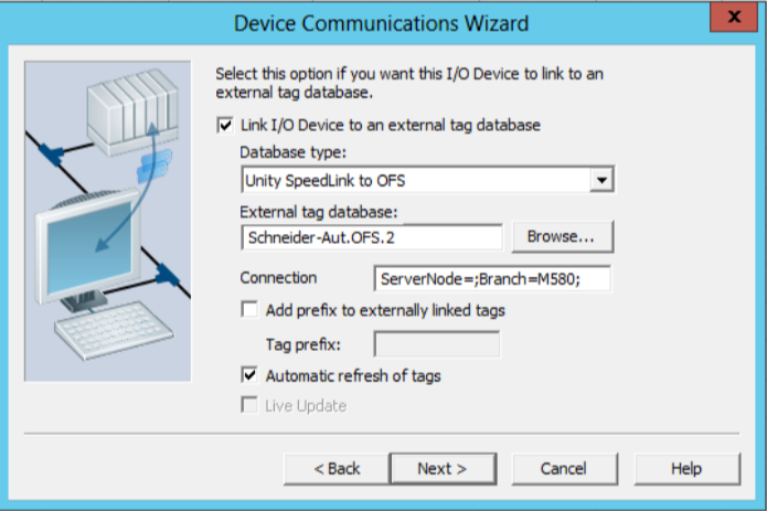
- Click Next.
- Review the summary. Click Finish to save the I/O device, or Back to change its settings.
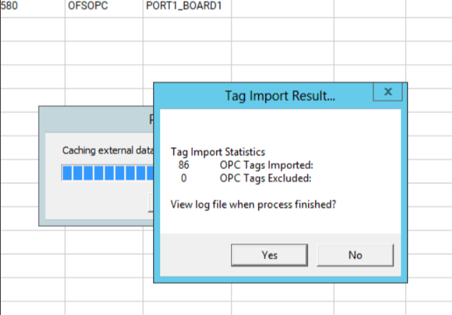
- Import the device tags:
- In Topology > I/O Devices, click Import Tags.
- Select the OFS I/O device, verify that the source information is correct, and then click Import. and then The PAC tags are then automatically updated through OFS.
- Create the equipment:
- In System Model > Equipment, click Equipment Editor.
- Add the Equipment and Equipment Types for the time stamped sources. For example:
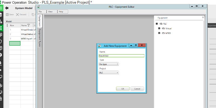
- Add a piece of equipment to associate with the I/O device:
- Click System Model > Equipment.
All of the device’s variables in this system will be linked to this equipment. For example:

- (Optional) Manually configure the alarm category. Alternatively, if you want to use an existing alarm category (_PLSALM_EVENT, _PLSALM_HIGH, _PLSALM_MEDIUM, or _PLSALM_LOW), skip this step.
To manually configure an alarm category:
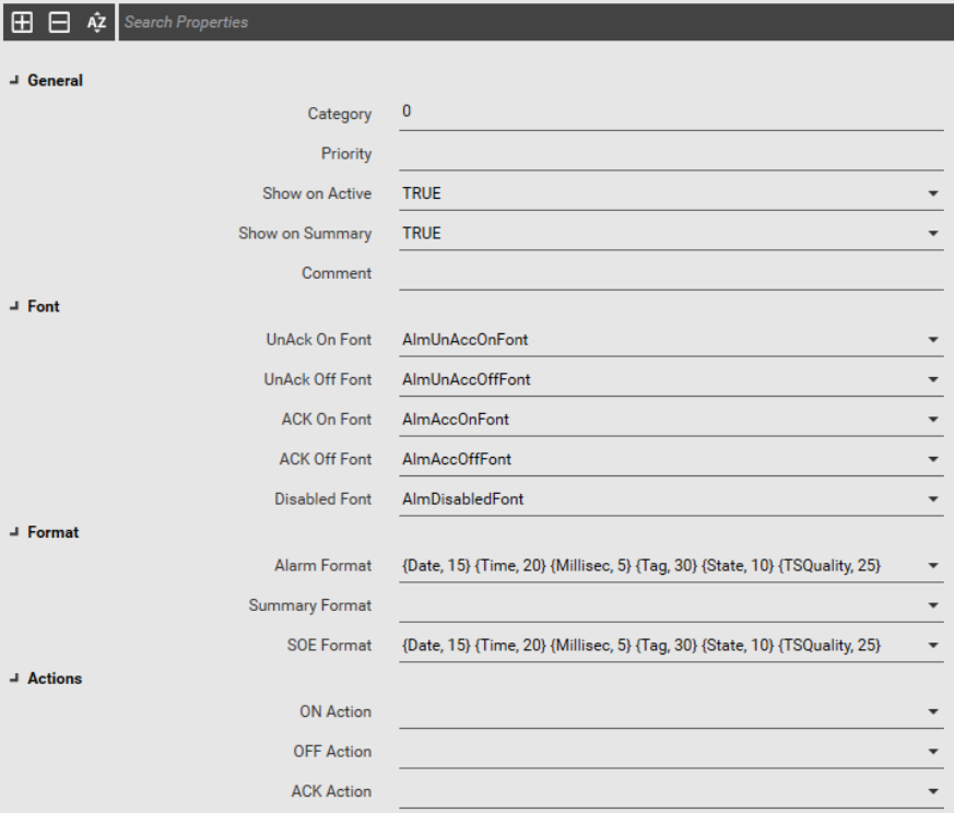
- Click Setup > Alarm Categories.
- In the grid, enter the Category number.
- Select whether the alarm category is Show on Active or Show on Summary.
- Select the corresponding formats for the different alarm statuses.
- In Alarm Format, enter the information to be displayed on the Active Alarm page, and, in SOE Format, the information to be displayed on the SOE history page.
For example:
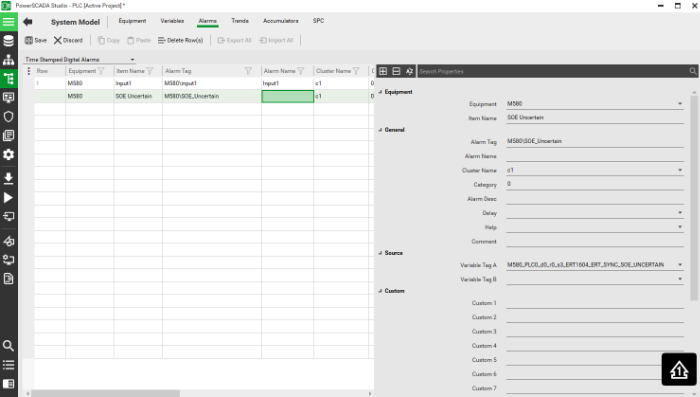
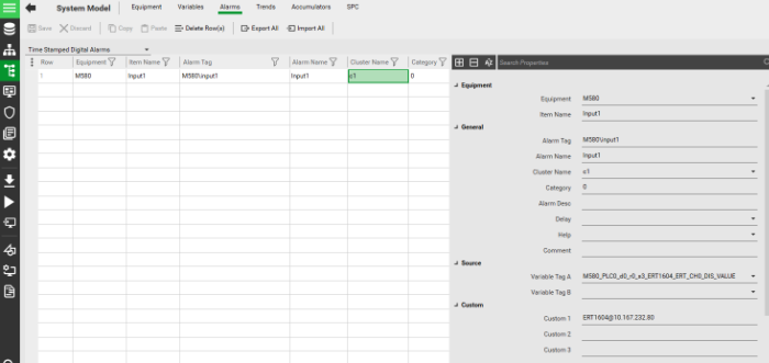
- Create the system time stamping alarms:
- Click System Model > Alarms.
- Select the corresponding Equipment for the alarm.
- Enter the alarm’s information, and select the time stamping variables to configure the Variable Tag.
- In the alarm Category, enter the alarm category you created in step 5, or select an existing alarm category (_PLSALM_EVENT, _PLSALM_HIGH, _PLSALM_MEDIUM, or _PLSALM_LOW).
For example:
 warning
LOSS OF ALARMS
● To be able to detect that the event buffer is full, configure a tag and an alarm tag associated with the SOE_Uncertain parameter in UnityPro. ● Respond quickly to a buffer full alarm if it appears, as this will avoid a situation where the buffer becomes inoperable. Failure to follow these instructions can result in death, serious injury, or equipment damage.
NOTE: When the source event buffer in the PLC is full, any new events will not be stored. In this case the value of SOE_Uncertain variable becomes TRUE. When the buffer becomes available again, the PLC will provide the values of all time stamped event variables. As these values are timestamped with a current time, the time quality of these values will be set to Invalid. The SOE_Uncertain is a variable in a time stamped event source whose value becomes TRUE when there is no space in the event buffer.
In other words, from the moment the SOE_Uncertain variable becomes TRUE to the moment it goes FALSE, all events occurring within that time period will have an invalid time quality. Do not rely on the time quality of events occurring within the time period where SOE_Uncertain is TRUE (event buffer full). - Add the ‘SOE_UNCERTAIN’ parameter to the ‘Time Stamped Digital Alarms’ to help check the status of the time stamping sources: