Interface overview
After you log in to Power Operation, and you launch the Power Operation Runtime, you see the individual landing page that has been created for this project. The Power Operation Runtime includes a banner and a variety of tabs that open graphics pages.
NOTE: The graphics pages that appear in the Power Operation Runtime are configurable and can vary greatly among projects. The pages that appear are defined by the Menu Configuration file for this project. If you need to change the appearance of tabs and menus.
If your runtime is based on the Normal template from the pls_include_1 library, the Power Operation Runtime banner consists of the following elements:
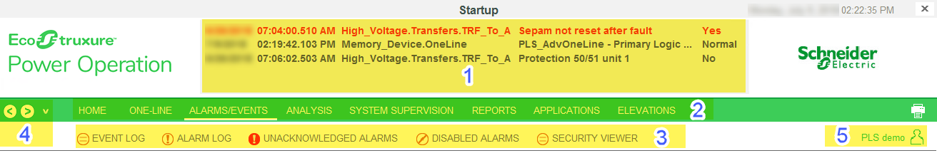
| 1 | The alarm banner. It lists the last five active alarms. |
| 2 |
Tabbed-style menu. Its contents are determined by the information entered in the Menu Configuration tool. If there are more links available than the ones that fit on the page, a small arrow displays at the right side of the row. Click the arrow to display a pop-up menu of the remaining links. Click a link in the menu to shift the contents of the row to make it visible for selection. The upper row is typically used for organizing pages into several topics (or tabs). A typical system would include topics for one-line diagrams, alarms/events, analysis (for trends), and system supervision (lets you view the network connection topics). |
| 3 | The lower row lists the links/pages under the topic that is currently selected in the upper row. If you select the one-lines topic on the upper row, the lower row displays all of the links to individual one-line pages. |
| 4 | These two arrows allow you to go back and forward one page in your navigation history. To see the history of visited pages, click the drop down arrow next to the right arrow. This displays a listing of visited pages (the current page is checked). To jump to a page in this list, click it in the menu. |
| 5 | The project name. The name of the user who is currently logged in. |
Viewing one-lines
If the busbars and circuit breakers do not display as expected, it could be that a custom genie is not set up correctly.
![]() danger
danger
equipment electric shock, explosion, or arc flash
| • | Do not rely solely on the display of the graphic on the one-line. |
| • | Verify that the device is physically locked out/tagged out before you work on the equipment or any downstream equipment. |
| • | Ensure that all safety regulations and procedures have been followed before you work on the equipment. |
Failure to follow these instructions will result in death or serious injury.
Communications loss
When there is a communication loss for a device, the genie or any part of the genie on the one-line page should have cross-hatches (gray dots) over the affected area, and a communication loss indication displays on the genie. An alarm should also annunciate. The color state before communication was lost will remain unchanged.
However, the indication of loss of communications does not filter through the entire bus animation: the downstream part of the drawing may still appear as if communication is working. When any part of a one-line drawing loses communication, do not continue to trust downstream readings until you address the loss of communication.