Read and Write Alarm Properties
Configure TGML to write the properties of alarms using web graphics. Configure TGML to display different alarm properties on web graphics.
Write alarm properties using TGML
You can write alarm properties, such as DataPoints.
To write alarm properties using TGML:
- In Graphics Editor, select on the Components tab.
- Expand Miscellaneous, select User Input Write Operation.
- While holding down CTRL, drag and drop the User Input Write Operation button to the work area.
- In the Properties pane, enter the fully qualified DataPoint value. For example, DataPoint: PLSDCluster.High_Voltage.Generators.GEN1.Ia.High includes the cluster name, equipment name, source name, and item name, followed by the Alarm property.
- Save the graphic file.
- In WebHMI, select on the DIAGRAMS tab.
- In the Diagram Library, select the saved graphic file.
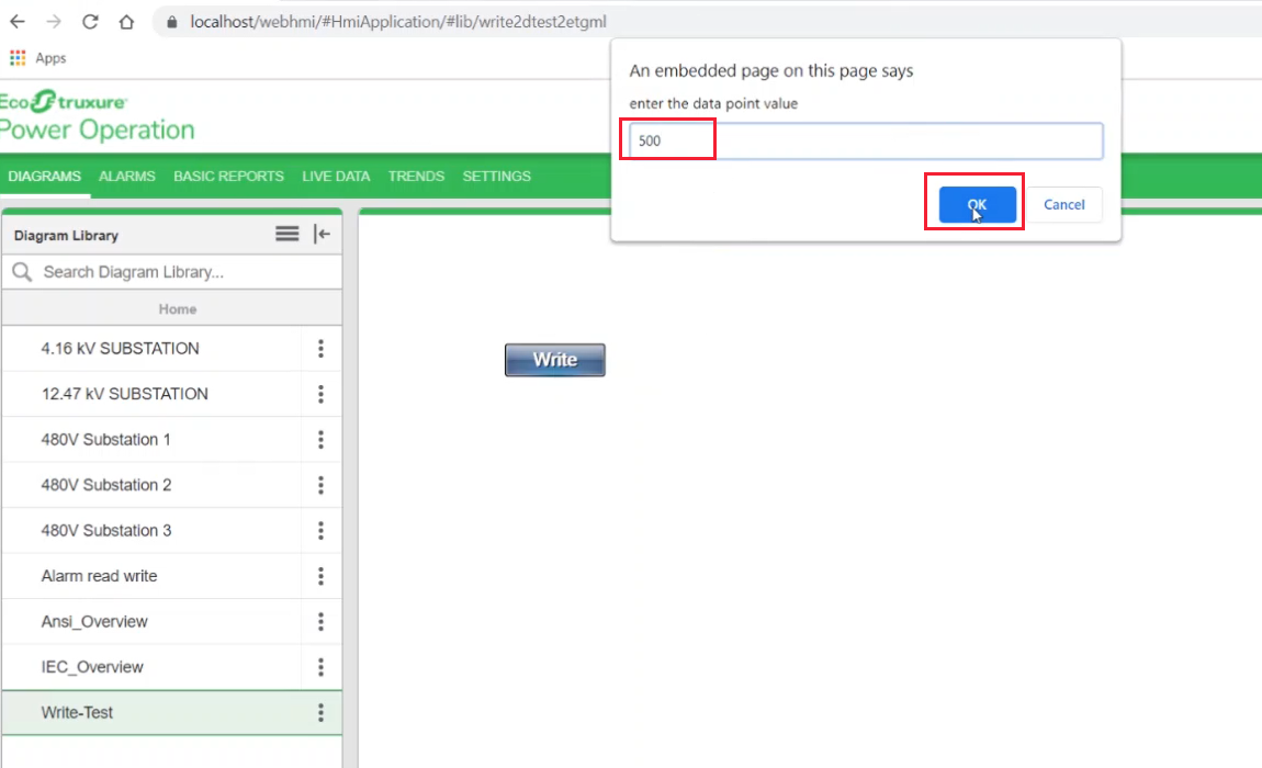
- In the dialog, enter the DataPoint value you want assigned to the alarm property and select OK.
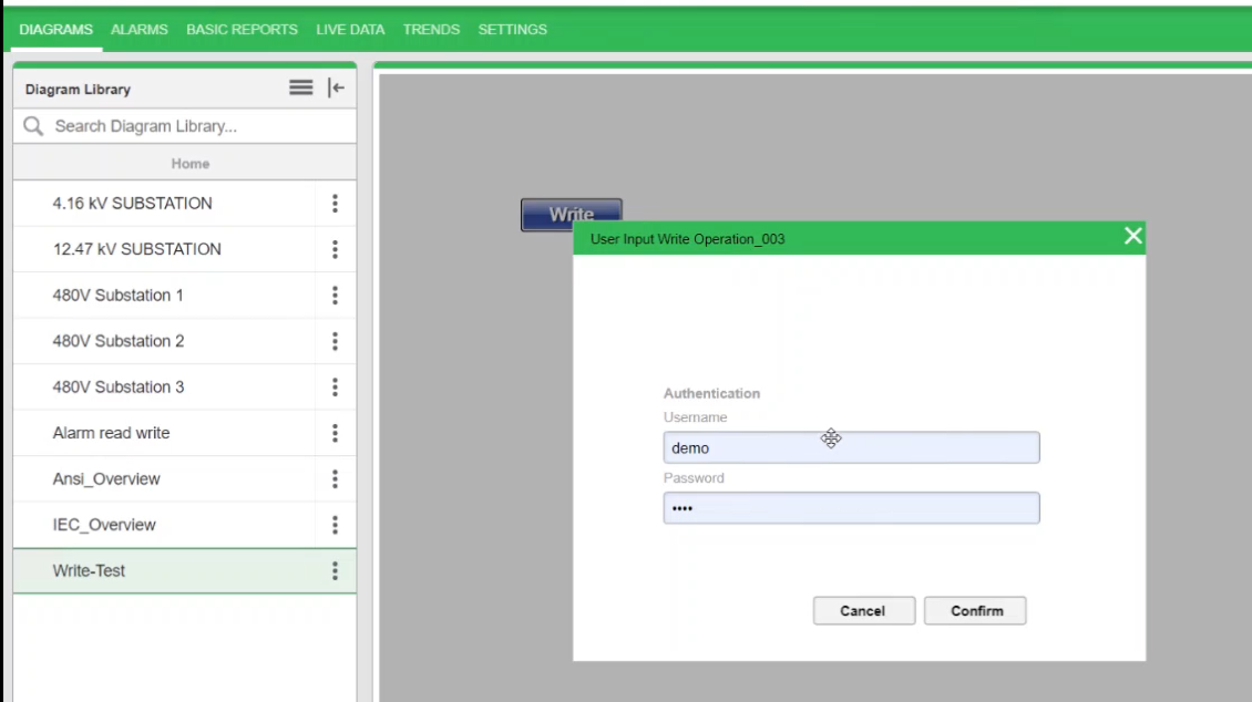
- In the Write Operation dialog, enter credentials and select Confirm.
Read alarm properties using TGML
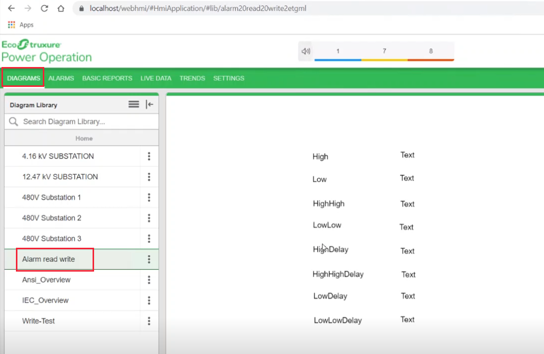
You can view the alarm property values on the DIAGRAMS tab.
To read alarm properties using TGML:
- In Graphics Editor, select the Text tool from the menu, place the cursor on the work area, and enter a name to act as a default.
- In the Properties pane, select Text.
- Right-click Text > New > Bind.
- Select Bind > Properties.
- Enter a property value.
For example: PLSDCluster.High_Voltage.Generators.GEN1.Ia.High.
- Save the graphic file.
- In WebHMI, select on the DIAGRAMS tab.
- In the Diagram Library, select the saved graphic file.
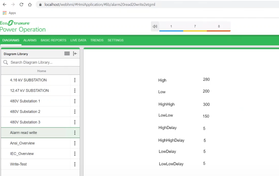
NOTE: Values will be displayed from the Read API.
Property values will be displayed based on how they were defined during the Write operation.
Alarm property keywords
-
High High - HighHigh
-
High High Delay - HHDelay
-
Low - Low
-
Low Delay - LDelay
-
Low Low - LowLow
-
Low Low Delay - LLDelay