Frequently Asked Questions (FAQs)
The following items provide information about topics that generate frequent questions.
Where can I get PDF versions of this help?
The Print version section in About this help includes information about where you can download a PDF version of this help.
Where can I find previous versions of this help?
|
Power Operation version |
Language |
File type and navigation |
|
EN |
Online help. Click the link provided. | |
| Power Operation 2021 Help | EN | PDF version only. The PDF version of this help can be downloaded from se.com by searching for the following: 7EN02-0462 |
If I don't use PowerLogic drivers, how do I create device profiles?
Create a device type using a non-PowerLogic driver (like MODNET).
- Using that device type, create a device profile.
- You need to change the addressing of the new device type. Copy the addressing from a known device type, and then make the necessary changes for the new device type.
How should we manage categories and subcategories?
We recommend that each integration team decide in advance which categories and subcategories they will use. The I/O Device Manager requires the entire Profile name (which uses the category and subcategory as part of its name). Thus, you must be consistent in naming if the profiles are going to be shared and re-used.
- Category should be used for a vendor.
- Subcategory should be used to describe a type of device.
- From the primary computer that has the Profile Editor installed, create the categories and subcategories that you plan to use.
- Copy the DeviceTypeCategories.xml file (located in the OS-specific data directory: Data/Profile Editor/ Vx.x ) to every computer being used to create profiles.
When should I create a device type rather than device profile?
Create a new device type, instead of a profile, when the addressing for a specific tag needs to change. For example:
The integration team can choose the Input to which they will wire circuit breaker status and position. In this case, the tags for circuit breaker status and position would have different addressing, based on how that particular circuit breaker is wired. We recommend a new device type in this case.
How do we synchronize a new PC with the primary Profile Editor PC?
To synchronize a new machine with the latest device types and profiles from your primary Profile Editor PC, you can:
- Use the Import feature to import tags, device types, and profiles from either an existing project or from SCL files.
- On the source PC: From the OS-specific Data/Profile Editor/ Vx.x directory, copy the entire OS-specific Data/Profile Editor/ Vx.x directory to the corresponding directory on the destination machine.
What do I do before I add or remove devices in the I/O Device Manager?
- Close all open DBF files.
- Click pack database after removal on the last page of the wizard.
If you are removing a device:
NOTE: Any changes that you made inside the Power Operation Studio (such as setpoints or data type modifications) are lost when you delete the device from Power Operation.
What are the requirements for device names?
Device Name:
Keep Device name ≤ 16 characters. Use _ as a separator.
If you use a naming convention that incorporates location, you will be able to do filtering on alarm location.
For example, Site_Building_Panel_device would be named Sx_Bx_Px_Device. (Site1_Building1_Panel1_CM41 — S1_B1_P1_CM41).
The fewer levels you have, the more characters you can have in each level.
Device Comment:
Use this field as an alias for the device name.
This comment will be placed in the Equipment database, which is accessible from Cicode.
How do I troubleshoot device communications issues?
Power Operation drivers provide default communication settings that work with most devices. However, in cases when communication losses occur, use this checklist for finding the issues.
Initial checks, if the device is attached via a gateway:
□ Ensure that all communication settings are correct on the gateway and device.
□ Check the gateway timeout. A setting that is too low will cause many timeouts to occur. A setting that is too high will impact performance. We recommend a 3 second timeout, because most devices work well with this setting. Some devices may require a higher timeout (5 seconds).
In all communication setups (also see the driver help for parameters):
□ Ensure that the Power Operation driver timeout is correct. We recommend that you set this to:
gateway timeout x number of clients + padding
Example: If the gateway timeout is 3 seconds and there are 3 clients, set the timeout in Power Operation to 10 seconds.
□ Check the maximum block read size. Some devices do not handle large block reads well. When you lower the maximum block read size, the requests are smaller and faster. The downside is that more requests will be sent to the device, and tags will refresh more slowly.
□ Check the device to see if there are registers that it cannot read. Some devices do not allow access to all registers.
Example: Data is in register 100-125 and 130-150. Power Operation will perform one read from 100-150. If 126-129 do not allow reading, this packet will return an exception. Use the appropriate logic code to mark these registers as invalid reads.
□ If there are still timeout/no response issues, enable retries on exception. Some devices may not respond if they are performing other functions. In this case, a0x0A or 0x0B exception will be returned to Power Operation, which will cause a communication loss. Enabling the "retry on exception" will re-try the request.
How do I use Modbus communications methods?
Modbus TCP/IP using Gateway: Use this for any device that is not configured to use TCP/IP communications protocol. These devices connect through a gateway device such as an EGX or ECC.
Modbus TCP/IP: Use this for any device that is not configured to use TCP/IP communications protocol. This includes CM4 or PM8 devices that have an ECC card installed.
How can I add more than one device at a time?
The I/O Device Manager requires that the profiles have already been exported from the Profile Editor to the project.
If the CSV file you use to add multiple devices attempts to add a device that is already present in the project, an error will be thrown.
In the event that an error is thrown (for invalid profiles, communication parameters, etc), the row containing the error will display in Excel. To prevent duplicate device entries from being attempted, you must remove any rows above the row indicated in the error message.
If you need to keep a record of the devices added to the system, then keep each of the spreadsheets that was used to install devices in a known location for that customer.
The Setup Sheet needs to be modified for each project. Specify the entire path for each file.
The Input Sheet requires the following:
The entire path name for each profile. The path name for a profile is based on the category and subcategory from the Profile Editor.
Example: Schneider Electric.Monitoring Device.Branch Circuit Monitor Full
What are the naming conventions for servers and clusters?
There is no enforced naming convention for server and cluster names, other than the restriction that each server name and cluster name must be unique. Cluster names must be a maximum of 16 characters, contain no spaces, and cannot begin with a number.
Each team should come produce a naming convention for the servers and clusters. Consistent naming makes it easier to edit or create the automation spreadsheet used for device addition.
How and when do I create users for the Runtime environment?
New projects do not have any users created by default.
The default graphics objects (such as circuit breakers and alarm pages) are constructed using a pre-defined set of user privileges the security grid). During development, you must have users of various privilege levels for testing purposes. Create users for each of the various levels according to the security grid. To make the best use of these privileges, we recommend that you use this security grid when adding users as you create new projects.
For additional information, see Using Security in the citectSCADA.chm help file ( ..\Program Files (x86)\Schneider Electric\Power Operation\v2024\bin\Help\SCADA Help).
How do I manage projects in the Power Operation Studio of Power Operation?
Although the Project Designer might want to organize each project in a particular way to suit customers' needs, the following is a recommended best practice:
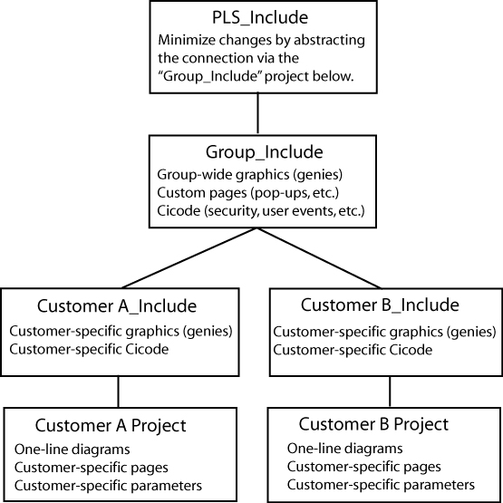
- Keep original ‘primary’ copies of the PLS_Example and the PLS_Include projects for reference.
- The Services Group may develop a group-wide “include” project that will act as a conduit between the PLS_Include project and all customer projects (for example: "Group_Include"). This will make the upgrading of PLS_Include much easier, as it will be the only project that must be modified to be compatible with the new version in the group-wide include project.
- When a new customer project is started, also create a customer-level “include” project.
- Upgrading PLS_Include:
Any changes made to the PLS_Include project should be made at the Group_Include project level. This would involve removing portions of the code from the PLS_Include project, modifying the code and saving it in the Group_Include project. By removing (or commenting out) the original code and placing the new code in the Group_Include project, a layer of abstraction is preserved, further simplifying the upgrade process. In other words, the only changes to PLS_Include should be code removal.
Always back up and restore the customer project and its associated include projects together.
Always restore include projects before restoring the customer (or top-level) project.
Document all changes to PLS_Include. This is absolutely necessary when upgrading to a new version of the PLS_Include project.
Minimize changes to the PLS_include project.
Abstract as many changes to the PLS_Include project as possible. Use multiple include projects as shown in the diagram previous.
New versions of PLS_Include will include a detailed description of each change, allowing you to merge the old and new versions.
New versions of PLS_Include will be backward compatibility, where possible.
On the Graphics page, what do I need to know about creating genies?
Creating a new genie
The easiest way to create a new genie is to use an existing genie from the library. This ensures that the new genie is compatible with the system, and that it preserves this feature:
A sizing guide (a dotted rectangle) is included; it displays during graphics edit mode. This guide ensures that new genies can be swapped with existing genies without the need to recreate portions of the drawing. Save the new genie in the appropriate project (do not overwrite the provided genies).
Save the new genie in the appropriate project (do not overwrite the provided genies).
Copying a genie to another project
Open the genie in the graphics editor, and do a <save as> into another project/library.
Genie Form Files
Any new genie (copied or created) will not have an FRM file entry associated with it. While the new genie is functional, it will show a cryptic unformatted properties box in the Graphics Editor. You can create your own FRM file with the needed entries by following the instructions available in the Power Operation Studio Knowledge base.
If you want to use the FRM dialog box that belongs to the genie you copied, go to the PLS_Include library; locate the CTM and FTM files. Each library has its own CTM/FTM files that include the description for every genie in the library. (This is an ASCII text file that you can open in any text editor.) Find the genie that you copied (or on which you're basing the new form). Copy the portion that matches the copied genie, and create an FRM file that has the desired library name on it. Copy in the text from the FRM file. Restart Power Operation Studio, or it will not detect the new FRM.
Genie Sizing
The provided genies come in two sizes: size 1 and size 2. When making a new genie for reuse among multiple projects, it will be beneficial to create a genie for both sizes. Follow the same steps for both sizes (sizing guides are provided for both sizes).
How do we customize existing templates?
Template Editing
All objects on the page contain one or more Animation Numbers (ANs). Symbols take one AN while genies may take tens to hundreds of ANs. Placeholder ANs allow you to add objects to a template that is used on existing pages.
Some default templates contain ANs that have associated Cicode functions that rely on the animation number to remain a fixed number. For this reason, we have pre-allocated a set of ANs for the default templates. The base normal template uses ANs 1–263, and it has placeholder ANs from 264–500. When customizing this template, you should use the placeholder ANs as required.
You can place an AN (or a placeholder AN) on the page by using the “System 3.x/4.x tools available in the Graphics Builder under Tools < Options.
The default template uses ANs 1–263 and it has placeholder ANs from 264–500.
New objects added to a page or template will take the next available ANs. Any previously used (and now abandoned) ANs will be reused.
To add an object on the template:
- Open the template.
- View the page properties and change the page width to 2000. This will reveal the hidden placeholder ANs on the page. You may have to change the width to a wider dimension for widescreen templates.
- Determine how many ANs the new object requires. (You can place the new object on a blank page and then view the object in the object browser.)
- Remove exactly the amount of ANs to allow the new object to be placed on the template. Remove ANs beginning with the lowest available placeholder AN (in the default template, this would be 264).
- Place the object on the template.
- Save the template.
- Create a new page based on this template.
- Drop a numeric object on the page.
- This object’s AN should be 502 (501 is reserved for placing the template on the page).
- If the object has an AN less than 502 then you have unused AN(s) on the template. This must be resolved. (Place additional ANs on the template to rectify this situation.)
- If the object has an AN greater than 502 then you have too many ANs on the template (a AN on the template is going beyond the 500 limit). You must find the culprit (via the object browser) and rectify the situation using the steps previous.
How do I change the default pickup/dropout text for alarms?
The default ‘pickup/dropout’ text is shown as Appearance/Disappearance.
To change globally:
This text can be changed by configuring INI parameters in the citect.ini file. For more information, see the Power Operation 2024 Help Manual(Graphics Library Parameters).
This is the global fallback text that will be used if pickup/dropout text is not specific on a per-alarm basis in the Device Profile. You can specify the per-alarm pickup/drop-out text on the profile tab in the Profile Editor.
To change on an individual basis:
See the Power Operation 2024 Help Manual (Viewing Device Profiles: "Alarm On Text" and "Alarm Off Text").
What can I modify during runtime?
See the Power Operation 2024 Design Guide, "Updates to the System While Online," for a list of items you can modify during runtime.
Why do the browser navigation buttons not work?
If the browser navigation buttons do not work when you are viewing the runtime window, you have probably added a new page, but have not done the following:
Added the startup page to the Page parameter.
Left the INI settings at <default>. In the Computer Setup Wizard, General Options Setup screen, do not change the StartupPage field; leave it as <default>.
What can I set up in logging and archiving?
Event Logging and Archiving:
Event fields that are logged to disk may be configured by adjusting the AlarmFormat parameter.
There is no automatic maintenance performed on the log files. It is important that the log/waveform data be cleared out periodically (to prevent the hard drive from filling up; this does not affect performance).
How do I create and configure busbars?
When drawing one-line diagrams:
Analyze the drawings at a customer site.
Number the busbars consistently on the one-line diagram(s). If busbar 14 spans across multiple pages, it should be numbered busbar 14 on all pages. Label the voltage level (0–3) on each busbar.
Uses for Line Active:
Page Connections: Many one-line diagrams will span multiple pages. To connect these pages together, you must use the line active field of the ‘incomers’ of the second and subsequent pages. Set the line active field of the incoming busbars on these pages to an expression that references the nearest device on the same busbar of the previous page.
Metered Busbar: Many busbars are metered. It is more accurate to allow these metering devices to dictate state than to rely solely on the simulation (see Expressions below).
Configuration of Line Active:
Simulation: If the Line-Active field is left blank, the busbar state will be determined by surrounding devices.
Expressions:
A Cicode expression in the form of Device\Tag > Nominal Voltage (I.E., S1_B1_P1_CM41\MMXU1\PhV\zavg > 120).
If the expression is TRUE, the ACTIVE color will be shown. The active color is determined by the voltage level assigned.
If the expression is FALSE, the DE-ENERGIZED color will be shown.
Hard-Coded
If no upstream devices are available (in the event of an incomer, for example), you may have no other choice than to ‘hard code’ this field to a ‘1’. This forces the busbar to always be ACTIVE.
What INI parameters should I use for debugging?
We recommend that you contact Technical Support before performing any debugging.
Parameter: [PowerLogicCore]
DebugCategory = All
DebugLevel = All (or Error)
LogFileArchive = Deprecated; no longer used. Use [Debug]SysLogArchive instead.
LogFileSize = Deprecated; no longer used. Use [Debug]SysLogSize instead.
Parameter Details:
DebugCategory defines which message categories to log. (See table below).
DebugLevel defines debug levels of messages to be logged. (See table below).
Debug Levels
The following debug levels are accepted by PowerLogic driver core library:
- WARN: log all warning level messages
- ERROR: log all error messages
- TRACE: log all trace messages
- DEBUG: log all debug messages
- ALL: include all level messages
Debug Categories
PowerLogic core library and driver messages are grouped in categories. Each of these categories can be enabled independently from others in any combination.
- ALL: enables all categories
- ALARM: messages related to alarms, regarding collection and detection
- COMMAND: messages related to commands
- CORE: core events that do not fall into driver-specific logic
- DATAPOINT: debug messages related to data points
- ENTRY: trace messages produced when driver API entry points are called
- MISC: miscellaneous messages that do not all into any other category
- MODBUS: TCP/MODBUS messages
- PORT: traces related to the port events
- REAL: messages related to real-time data collection
- REPLICATION: messages produced by replication subsystem
- STATE: messages related to internal object-state changes
- STATISTICS: enables driver statistics data output
- UNIT: traces related to specific unit events
- WAVE: messages related to waveforms -- waveforms download, processing
- WAVETOALARM: not used
Parameter: [Debug]
Menu = 1
Parameter Details:
The Menu parameter determines whether the Kernel option is displayed on the control menu of the runtime menu. This can also be enabled using the Computer Setup Editor.
How do I tune my system for best performance?
There are several parameters you can use to enhance your system's performance:
Driver-tuning parameters:
Parameter (Back Polling Rate): [SEPAM40]
CacheRefreshTime = 1000
InitUniCheckTime = 120
Retry = 3
Timeout = 1000
Parameter Details:
The CacheRefreshTime parameter controls the maximum rate at which the driver will attempt to repopulate its cache. If the driver cannot refresh its cache within the time specified, it will collect data as fast as the network allows.
This back polling rate can be global to all devices or tuned up to a specific I/O device.
The InitUniCheckTime parameter controls how long the driver will wait before attempting to bring a device online after it has gone offline. This value can be decreased to bring offline devices back into service in a shorter period of time. In a multi-drop scenario, this time should be relatively long, to prevent init unit requests from stalling communications to the rest of the devices on that port.
The Retry parameter defines the number of retry attempts for specific MODBUS requests. Retries will only occur in response to the MODBUS errors which are defined below.
The Timeout parameter controls how long the driver will wait for a response from a device before setting that device as offline. This value should be greater than the device/gateway timeout period.
Parameter: [Device]
WatchTime = 5000
Parameter Details:
Device WatchTime is the frequency that Power Operation checks devices for history files and flushes logging data to disk.
Default: 5000
Range: 1000–3600000 milliseconds.
Miscellaneous Parameters
Parameter: [Kernel]
Task = 20000
Parameter Details:
Kernel Task is the number of tasks. Increasing the number of kernel tasks is used when “Out of Kernel Task” message is received. The change will be likely for large systems.
Default Value: 256
Range: 50–32767
Parameter: [Page]
ScanTime = 250
Parameter Details:
Page ScanTime determines how often the Animator refreshes a graphics page at runtime.
Default: 250
Range: 1–60000 milliseconds
Parameter: [ALARM]
ScanTime = 500
Parameter Details:
Alarm ScanTime determines the rate at which alarms are scanned and processed.
Default: 500
Range: 0–60000 milliseconds
If a tag is configured, how is it polled in the device?
In other words, is a tag only polled on demand when it is requested by a client; for example, when the operator displays a page with the tag on it? Or are all configured tags polled all the time, with the relative polling rates/communications bandwidth carefully managed?
The ModNet driver polls real-time tags on a user demand basis (when a user opens a page with the tags on it). Therefore, the time to retrieve data will vary, depending not only on the communications bandwidth, but on the amount of data being requested. This can vary significantly, depending on which pages are displayed by the operators at any particular time.
The PWRMODBUS driver polls all configured tags; however, different types of tags can be polled at different relative rates, and the available communications bandwidth is carefully managed. This approach means that tag update rates are not subject to the scalability issues associated with operator actions (as is the case for the ModNet driver). It is also advantageous in that performance issues associated with communications bandwidth or I/O device response times can be determined at SAT/time of implementation and are not subject to significant change during operation.
The different tag types can be allocated relative importance in data requests, expressed as a percentage. (See Bandwidth Allocation Parameters in Performance Tuning Parameters, in the Power Operation 2024 Help Manual. Keep in mind that any unused bandwidth allocation (from, for example, events retrieval) is made available for other data types to use. If the event does not need the default 25% allocation, it will be made available to the other parameters (real-time tag retrieval, etc). This potentially increases the update rate of real-time tags.
Additionally, the real-time tag relative scan rate based on priority can be set to three different levels. (See "Tag Scan Rate Parameters" in Performance Tuning Parameters, in the Power Operation 2024 Help Manual.) This means that, if some real-time tags are more important that others, you can set their relative priorities. For example, configuration tags vs. important real-time tags vs. normal real-time tags.
Device popup from a one-line: Why do the fields overlap?
This is controlled by a parameter entry:
Section: Page
Name: EquipDetailDescLength (the total number of characters in a single row of this popup)
Default = 48. The problem will occur with a larger font or if the window is resized. The default value of 48 can be changed or the window and associated genies can be resized.
Can I change the %CLUSTER% name in the I/O Device Manager?
No. If you change the placeholder %CLUSTER% to any other name in the I/O Device Manager, the system will be unable to find the actual cluster to which it refers.
A device can prevent writes to its registers: how do I ensure that writes are successful?
Power Operation cannot provide feedback about whether a write to a device register is successful. If a device is capable is preventing (blocking) writes to its registers (for example, Sepam), you need to verify that its “block” feature is not enabled. Do this at the device.
In Cicode, you can also use the tagwrite function in blocking mode, i.e., bSync parameter = true; Check the return code: 0 = success, anything else = error. For more information, see the Cicode Programming Reference help file.
How do I prevent Power Operation from accidentally making invalid areas in memory available to reads and writes?
Power Operation normally optimizes its packets for greatest performance. This optimization can sometimes include invalid areas of memory in devices. These invalid areas can be specifically defined and excluded from optimization packets created by Power Operation. For more information, see "Advanced Tag Blocking Capabilities" in Performance Tuning Parameters, in the Power Operation 2024 Help Manual.
How do I create an audit in the Event Log for user logins and logouts?
//LOGOUT

FUNCTION
PLSLoginUser()

//INT iPage = PageInfo(1);
INT iPage = WinNumber();
IF 	mbLoginFormShown[iPage] = TRUE THEN
RETURN;		//form already shown
END
//prevent multiple forms
mbLoginFormShown[iPage] = TRUE;
IF (UserInfo(0) <> "0") THEN
// Confirm User Action
IF (0 = Message(StrToLocalText("@(Confirm)"), StrToLocalText("@(Logout)"), 1+32)) THEN
PLSAlmDspEventAdd(0, 0, 1, "User Logout", Name(), "Logout", "");
Logout();
END
mbLoginFormShown[iPage] = FALSE;
RETURN;
END
IF (0 = LoginForm())
PLSAlmDspEventAdd(0, 0, 1, "User Login", Name(), "Login", "");
END
mbLoginFormShown[iPage] = FALSE;
END
Why am I seeing #COM for circuit breaker status in the genie status page?
If this is a Micrologic P device, and it does not have a CCM, you will not be able to view data referring to circuit breaker status, e.g. racked in/racked out. When there is no CCM, the device profile should not have tags that refer to the CCM.
Why can't I acquire waveforms in the waveform viewer?
The "acquire" feature (the "A" button on the waveform viewer) does not work in Power Operation. You can, however, view waveforms from device onboard waveform files. To do this:
At the device or in the meter configuration software, add the appropriate alarm, and enable automatic capture of the waveform when the alarm occurs.
In the Profile Editor (Create Device Profiles tab), check the Waveform box for the alarm you added.
When the alarm occurs, the waveform is captured. You can view the waveform in the Alarm Log. You can also view alarms/waveforms from a drawing in the runtime environment. Click the genie for the device; right-click the alarm to view the waveform.
Note that, in very large systems, it could take as much as an hour for the waveform to appear.
Why won't the Excel DBF Add-In toolbar install?
When you are installing the Excel DBF Add-In toolbar, you may see this error: "Error 1308. Source file not found....."
You can click "ignore" at this error, and the install will finish. The next time you open Excel, the DBF toolbar will display.
What causes the "First dbf record" error message? How do I keep it from happening?
The error message "First dbf record" tells you that a project is not found. This happens when you add a project, and then rename it or delete it. Then, when you try to create a new project, you see this error message.
To resolve this issue, simply shut down and then restart the Power Operation Studio.
Why is my device in comms loss?
When you bring your system on line, and you find that Power Operation has lost communications with a device, check the following:
Verify that the physical correction is correct and secure.
Verify the IP address.
Verify the Modbus address.
Check the statusRegister, statusRegistersCount, and statusRegisterType (see for details)
How do I set up select before operate?
For systems in which you can determine that a single user is selecting a device prior to sending an open/close command, you can add a "select before operate" button.
To do this:
- Locate the Select Before Operate tag in the variable tags.
- Append
\strto the end of the tag name. - Change the data type to STRING.
- Click Add.
This creates the SBOw tag for the IEC 61850 advanced control screen. For more information about advanced control.