Manually simulate breaker components
To manually simulate a breaker component using its exposed properties:
- In Graphics Editor, in a TGML page, set the required value in the exposed property of a breaker component.
- Use the allowed values, as shown in the table below.
- Save the TGML and create the configuration file from Connection Debugger tool.
| Binding name | Exposed attributes | Values allowed for exposed attributes | Comment |
|---|---|---|---|
| IsClosed | ActiveCondition | 0 & 1 | 1=Closed |
| IsOpen | BkrOpnCond | 0 & 1 | 1=Open |
| IsError | BkrErrCond | 0 & 1 | 1=Bad/Error |
| IsInter | BkrIntCond | 0 & 1 | 1=Intermediate |
| RkdPos | RkdPosCond | 0 & 1 | 0=Racked-In
1=Racked-Out |
| IsTripped | TripCond | 0 & 1 | 0=Normal
1=Tripped |
| EarthSwitchClosed | EarthSwitchCond | 0 & 1 | 0=ES Open
1=ES Closed |
For example, to manually simulate breaker operation by setting exposed attributes for the selected breaker component, do the following:
| Scenario 1 |
With breaker closed, racked-in and earth switch open ActiveCondition=1, BkrOpnCond=0, BkrErrCond=0, BkrIntCond=0, RkdPosCond=0, TripCond=0 and EarthSwitchCond=0 |
| Scenario 2 |
With breaker open, racked-out and earth switch closed ActiveCondition=0, BkrOpnCond=1, BkrErrCond=0, BkrIntCond=0, RkdPosCond=1, TripCond=0 and EarthSwitchCond=1 |
NOTE:
- If the non-rackable breaker components are configured for rackable breakers, then you may get undesirable animations when the physical breaker is held in the racked-out/Test position.
- Ignore setting the RkdPosCond and EarthSwitchCond attributes if the circuit breaker does not have these features.
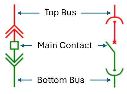
| Basic elements of Breaker Components |
|