Electrical Connections of the Lexium Cobot Arm
Supply Connection
For the Lexium Cobot Arm LXMRL03S0•••:
The power supply cable is included in the scope of delivery and one terminal side is pre-mounted on the Lexium Cobot Arm, in a length of 6 m (19.7 ft). On the other terminal side, the power supply cable is equipped with a connector to interface with the Lexium Cobot Controllers.
For the Lexium Cobot Arm LXMRL05S0••• / LXMRL07S0••• / LXMRL12S0••• / LXMRL18S0•••:
The power supply cable is included in the scope of delivery of the Lexium Cobot Arm, in a length of 6 m (19.7 ft). On both terminal sides, the power supply cable is equipped with connectors to interface with the Lexium Cobot Controllers. Use the angled connector of the power supply cable with the Lexium Cobot Controllers.

1 Connector CN1
End-Effector M8 Connector Interface
The M8 connector interface located at the side of the tool flange is used to control outputs and inputs on the end effector. Besides a DC power supply the following signals are provided by default by the interface:
-
Digital inputs: 2
-
Digital outputs: 2
-
Analog inputs: 2
In addition, the analog inputs and the digital outputs can be configured in EcoStruxure Cobot Expert to operate as RS485 network. For details on the configuration of the end-effector interface, refer to the chapter Terminal IO in the EcoStruxure Cobot Expert Software Guide.
| Characteristic | End-Effector interface |
|---|---|
|
Digital Inputs |
|
|
Number of digital inputs |
2 inputs (TDI1, TDI2) |
|
Pins on interface |
2, 3 |
|
Input type |
Type 1 |
|
Logic type |
Source or sink (configurable by application) |
|
Rated input voltage |
24 V dc |
|
High signal |
7...24 V dc |
|
Low signal |
0...4 V dc |
|
Digital Outputs |
|
|
Number of digital outputs |
2 outputs (TDO1, TDO2) |
|
Pins on interface |
4, 5 |
|
Output type |
Type 1 |
|
Logic type |
Source or sink (configurable by application), TDO1 and TDO2 can be used together as RS485 channel 1 |
|
Rated output voltage |
24 V dc |
|
Maximum output current |
1.0 A per output
NOTE: Verify that the total current of the end-effector interface is not exceeded.
|
|
Analog Inputs |
|
|
Number of analog inputs |
2 inputs (TAI1, TAI2) |
|
Pins on interface |
6, 7 |
|
Input type |
Voltage |
|
Input range |
0...10 V dc |
|
Logic type |
Source, TAI1 and TAI2 can be used together as RS485 channel 2 |
|
Power Supply |
|
|
Number of power supplies |
1 common supply for the interface connector |
|
Pins on interface |
1, 8 |
|
Rated output voltage available for end-effector |
Disabled, 12 or 24 V dc (configurable by application) |
|
Maximum output current |
1.0 A |
For connecting external sensors and actuators at the end-effector, you can use pre-wired cables equipped with an 8-pole M8 plug-type connector. For questions regarding applicable extension cables, contact your local Schneider Electric representative.
The following figure presents the socket-type M8 connector (S) at the Lexium Cobot Arm flange and the delivered extension cable equipped with an 8-pole M8 plug-type connector (P) with a length of 400 mm (15.7 in) and open ended (reference LXMRL00YY011).
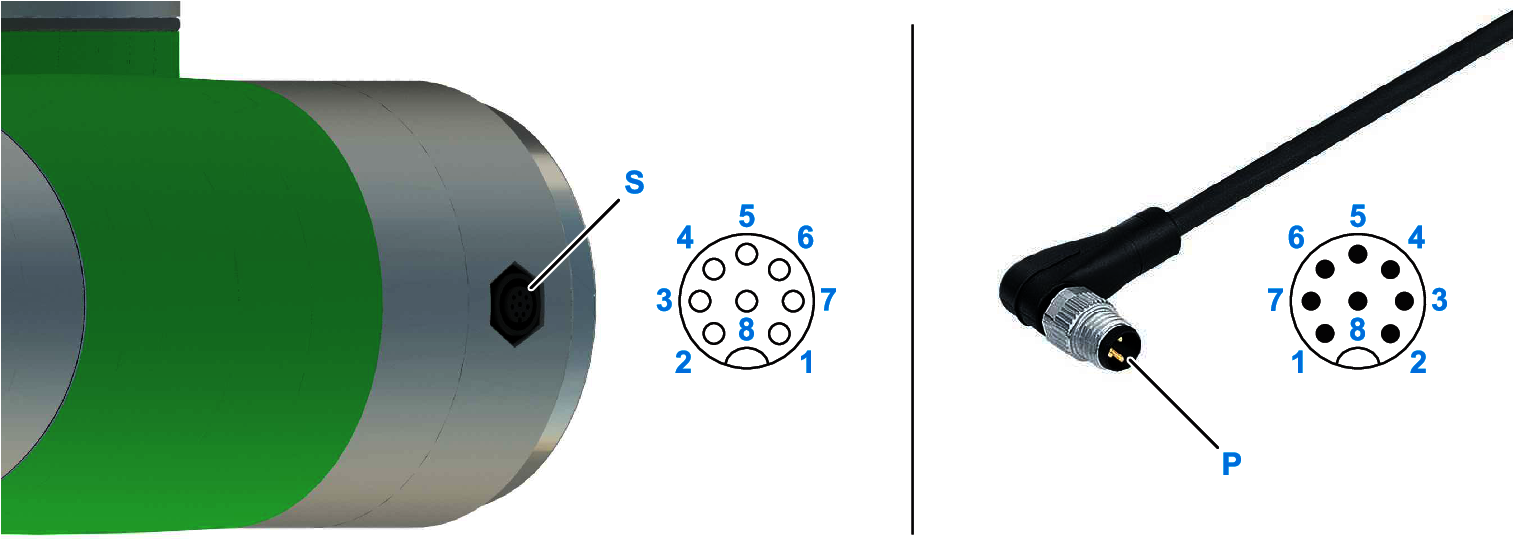
S Socket-type connector
P Plug-type connector
| Pin | Label | Wire color | Dedication | Description |
|---|---|---|---|---|
|
1 |
V+ |
red |
Power supply |
Positive supply potential, 12 or 24 V dc or disabled, configurable by application |
|
2 |
TDI1 |
blue |
Digital input |
Digital input 1, sink or source configurable by application |
|
3 |
TDI2 |
green |
Digital input |
Digital input 2, sink or source configurable by application |
|
4 |
TDO1 |
yellow |
Digital output RS485 channel |
Digital output 1, sink or source configurable by application, also configurable as RS485 channel 1 |
|
5 |
TDO2 |
pink |
Digital output RS485 channel |
Digital output 2, sink or source configurable by application, also configurable as RS485 channel 1 |
|
6 |
TAI1 |
brown |
Analog input RS485 channel |
Analog input 1, also configurable as RS485 channel 2 by application |
|
7 |
TAI2 |
white |
Analog input RS485 channel |
Analog input 2, also configurable as RS485 channel 2 by application |
|
8 |
0V |
grey |
Power supply |
Negative reference potential for V+ supply |
Digital Inputs
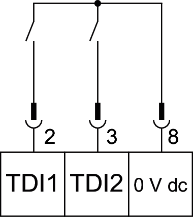
The following figure presents the sink wiring of the controller digital inputs. Sink or source can be configured on the digital input settings by the application.
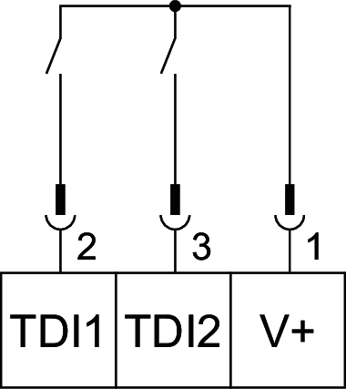
The following figure presents the source wiring of the controller digital inputs. Sink or source can be configured on the digital input settings by the application.
Digital Outputs
The following figure presents the source wiring of the outputs. Sink or source can be configured on the digital output settings by the application.
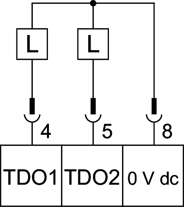
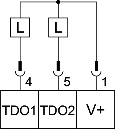
The following figure presents the sink wiring of the outputs. Sink or source can be configured on the digital output settings by the application.
RS485 Communication
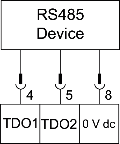
The following figure presents the wiring of the RS485 channel 1. RS485 communication can be configured on the digital output settings by the application.
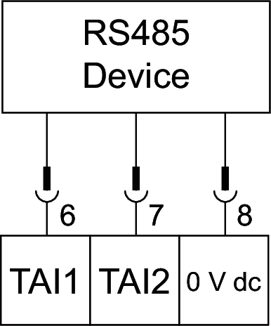
The following figure presents the wiring of the RS485 channel 2. RS485 communication can be configured on the analog input settings by the application.
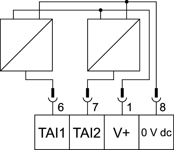
Analog Inputs
The following figure presents an example of an analog input wiring.