Content of the Catalog
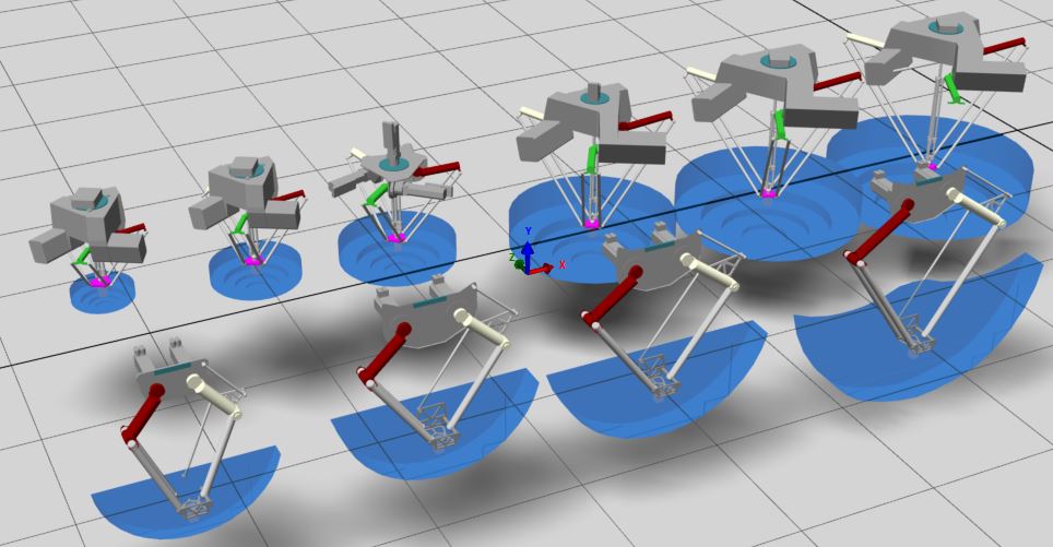
Select the catalog in the view to display the different types of Lexium P Robot and Lexium T Robot represented as subnodes.
Each subnode contains further subnodes which, in turn, represent a robot you can move to the view and use as assembly in your scene.
Details of Assemblies
A delta robots assembly is driven by reference values from a controller, for example, a PacDrive controller or a Modicon M262 Logic/Motion Controller. To this end, connect the joint values to reference values of an LREAL data type. Depending on the type of robot, a different number of axes needs to be connected. Lexium P Robot assemblies have three main joints (, , ) and an optional rotational axis (). The Lexium T Robot is equipped with two joints for performing 2D movements.
In addition to the values, a subnode is provided. To activate it, connect the signal of type BOOL to your controller. For status messages to the controller, connect the signal of type BOOL.
Properties of Delta Robots
Once you have added an object of the catalog to the view, you can select it and display the associated parameters in the view on the right-hand side of the EcoStruxure Machine Expert Twin screen. The properties of a assembly consists of different sections providing the parameters described in the following paragraphs.
Section
|
Parameter |
Description |
|---|---|
|
|
Indicates the subnode of the as defined in the catalog. |
|
|
Indicates the commercial reference of the . |
|
|
Indicates the default name of the . Click the field to edit the name and adapt it to your requirements. |
|
|
Indicates the ID as provided by the menu for this connection. |
Section
|
Parameter |
Description |
|---|---|
|
|
Indicates the section in which the selected is placed. To shift the to another section, open the list and select . Result: In the view, the is displayed as a subnode of . |
|
|
Indicates the name of the tab the is connected to. |
Section
|
Parameter |
Description |
|---|---|
|
|
Exclusive to Lexium P Robot: By default, the rotational axis positive movement direction is right, meaning it moves clockwise when you face the motor shaft. Select the check box to revert the movement and change to left, meaning it moves counterclockwise when you face the motor shaft. For further information, refer to the description of the parameter Direction in a Device Objects and Parameters User Guide of a Schneider Electric drive in the EcoStruxure Machine Expert Online Help. For example, the Lexium LXM62 Drive Device Objects and Parameters User Guide. |
|
|
Exclusive to Lexium P Robot: Configure the radius of the Tool Center Point (TCP) plate size (in mm). Value range: 50...75 mm |
|
|
Exclusive to Lexium T Robot: By default, the parallel linkage is mounted on the right side. Select the check box to mount the parallel linkage on the left side. |
Section
|
Parameter |
Description |
|---|---|
|
|
By default, the working space is displayed in the scene where the robot can position the TCP. Select the check box to hide the working space from the scene. |
|
|
Select the check box to display the coordinate system (based on the right-handed coordinate system) that is used in EcoStruxure Machine Expert on the tool flange of the robot in the scene. |
|
|
Exclusive to Lexium P Robot: Select the check box to display the boundary for the upper arms in the scene. |
Section
|
Parameter |
Description |
|---|---|
|
|
By default, the check box is selected and the is enabled. Select this check box to disable the : The is displayed in grey in the view and does not function. Physical properties are not available. |
Section
The , , parameters allow you to modify the angle (in °) of rotation of the assembly around the X, Y and Z coordinate.
Section
|
Parameter |
Description |
|---|---|
|
|
Select the check box to lock the position of the selected to help prevent it from being moved unintentionally. |
|
|
Enter the x, y, z coordinates (in mm) of the selected to modify the position. You can also use the fundamental mathematical operations (addition, subtraction, multiplication and division) to calculate the position coordinates. |
Section
|
Parameter |
Description |
|---|---|
|
|
Select one of the following : Click the button of the event to open a view where you can enter the programming code to execute when the selected event is detected. The view provides the same functions as described in the EcoStruxure Machine Expert Twin Getting Started User Guide. |
Section
|
Parameter |
Description |
|---|---|
|
|
Deselect this check box to hide the in the scene. |
|
|
If the check box is selected, select a color for the . |
Section
As a prerequisite for displaying trajectory lines, start the physical simulation.
|
Parameter |
Description |
|---|---|
|
|
Select this check box to enable trajectory plotting. |
|
|
If the check box is selected, select a color for the trajectory lines. |
|
|
Enter a time (in milliseconds) each trajectory line is visible in the scene. Default value: 2000 ms |