View
Overview
The view allows you to create passive and active between two or more body assemblies created with the Kinematization Menu.
The is configurable in the editor and allows you to lock, unlock or limit movement within the six degrees of freedom (DOF) individually.
For a joint, one reference is considered the stationary reference (rigid), while the other is considered the moving reference (physics). The moving and the stationary references of the joint must be located on two different body assemblies.
Example of a configuration in the :
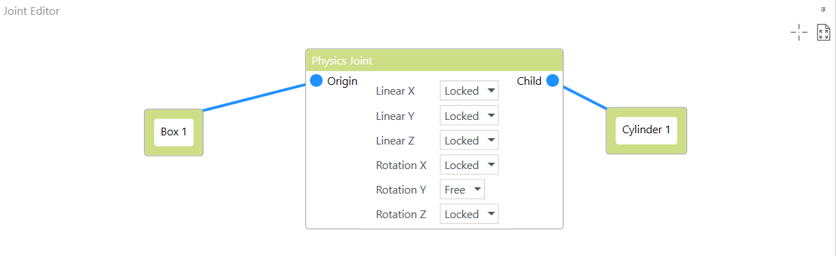
The editor automatically verifies the configuration and indicates detected configuration issues by a red triangle in each box that is affected. A tooltip is provided that indicates a solution. The total number of issues detected in the editor is displayed in the lower left corner.
The provides two buttons in the upper right corner:
|
Button |
Description |
|---|---|
|
|
Click to move the camera view of the editor to the upper left edge. |
|
|
Click to zoom in or out of the editor view so that all available objects are displayed. |
Creating Physical Joints
To create a physical joint between two assemblies, proceed as follows:
|
Step |
Action |
|---|---|
|
1 |
Right-click in the view and run the command from the contextual menu. Result: A new body block is displayed in the . |
|
2 |
Create a relationship between the block in the and an assembly in the scene by selecting the assembly in the scene or in the , right-clicking the block in the and running the command from the contextual menu. Result: The name of the assembly is assigned to the selected block in the . |
|
3 |
Repeat steps 1 and 2 to create a second block in the and to link it to a second assembly in the scene. Result: Two blocks representing two different assemblies are available in the . |
|
4 |
Right-click in the view and run the command from the contextual menu. Result: A block is added to the . |
|
5 |
Click in the frame of the first assembly, hold down the left mouse button and draw a connecting line to the connection point of the block. Result: The first assembly is defined as origin or stationary reference for the joint and the connection point is highlighted in blue. |
|
6 |
Verify the configuration of the body assembly that is connected as : The parameter must be set to or (refer to the Properties of Body Assemblies). If the = is selected, correct the configuration. |
|
7 |
Click the connection point of the block, hold down the left mouse button and draw a connecting line to the second assembly. Result: The second assembly is defined as child or moving reference for the joint, the connection point is highlighted in blue. |
|
8 |
Verify the configuration of the body assembly that is connected as : The parameter must be set to (refer to the Properties of Body Assemblies). If this is not the case, a red triangle is displayed at the upper right corner of the body block. To adapt the configuration, right-click the assembly that is defined as child and run the command from the contextual menu. Result: The parameter is set to and the red triangle is removed. |
|
9 |
Configure the . For further information, refer to Configuring Physical Joints. |
Configuring Physical Joints
By default, the six parameters representing the six degrees of freedom are set to , meaning that motion of the joint is not allowed:
To allow motion in one or more directions, select from the list for the respective parameters.
To restrict the motion of the moving reference for one degree of freedom, select and configure a force that corresponds to a spring to keep the body assembly within the defined limits.
The following constraints apply to the configuration of the with respect to the three axes and are restricted within the software:
|
Case |
Axis 1 |
Axis 2 |
Axis 3 |
Description |
|---|---|---|---|---|
|
Valid case 1 |
: -75°...75° |
: -75°...75° |
|
General rule: At least one axis must be to help ensure stability. If one axis is , allowed for the other two axes are between -75° and 75°. |
|
Valid case 2 |
: -180°...180° |
|
|
If two axes are , the allowed for third axis are between -180° and 180°. |
|
Invalid case |
: -75°...75° |
|
|
This is an invalid case because if one axis is . The software does not allow you set one of the other axes to . |
With selected, configure the following parameters:
|
Parameter |
Description |
|
|---|---|---|
|
|
Configure limits for the motion of the moving reference. |
|
|
|
Enter the maximum movement (in mm) in the negative direction for the remaining axis or axes if one or two axes are set to . The valid range depends on the configuration of the for the three axes of motion as indicated in the table above:
|
|
|
|
Enter the maximum movement (in mm) in the positive direction for the remaining axis or axes if one or two axes are set to . The valid range depends on the configuration of the for the three axes of motion as indicated in the table above:
|
|
|
|
Configure the physical properties that correspond to springs and that act on the moving reference to keep it within the configured limits. |
|
|
|
Enter a value >0 to configure the stiffness of the spring (in N/m) that is the extent to which it can resist deformation in response to an applied force. |
|
|
|
Enter a value >0 to configure the damping of the spring (in N·s/m) that is the resistance against fast changes in displacement and that contributes to bring the spring to rest quickly. |
|
|
|
Select this option to use active joints. Refer to Configuring Active Joints. |
|
By combining the physical joints feature with the functions provided in the menu, you can create customized robot kinematics.
Configuring Active Joints
You can also configure active or motorized joints that interact with the geometry by using forces. To achieve this, set the to or and configure the following parameters:
|
Parameter |
Description |
|
|---|---|---|
|
|
Select this option to use active or motorized joints to keep a moving reference within the configured limits. |
|
|
|
Select an option from the list to define the controller input that is valid for the motor:
The motor is configured with the parameter . |
|
|
|
Active joints are controlled by drives. The drive is a proportional derivative drive that applies a force according to the following formula: F = stiffness * (target position - position) + damping * (target velocity - velocity) |
|
|
|
Configure the motor according to the selection for the parameter . The motor parameters are configured as described in the How to Use Device Catalogs User Guide. Alternatively, you can right-click the motor node in the and control the motor manually with the , , , commands. |
|
|
|
Configure the coefficients used by the spring drive to move the child body assembly (moving reference) through forces. Use the parameter to apply a force that is proportional to the detected position error. Use the parameter to apply a force that is proportional to the detected velocity error. |
|