Functions of the Blocks
Overview
The blocks you can insert in the provide different functions. This chapter provides further information on available blocks.
Blocks
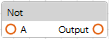
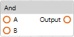
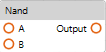
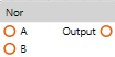
blocks are logical operators that perform operations using Boolean input values.
The following blocks are available:
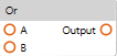
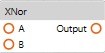
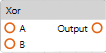
input and output signals:
|
Input signals |
Output signals |
Result |
||
|---|---|---|---|---|
|
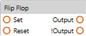
Set |
Reset |
Output |
!Output |
|
|
FALSE |
FALSE |
Output |
!Output |
If both input signals are FALSE, the output signals do not change. |
|
FALSE |
TRUE |
FALSE |
TRUE |
A reset is performed: Output = FALSE !Output = TRUE The state is retained. |
|
TRUE |
FALSE |
TRUE |
FALSE |
A set is performed: Output = TRUE !Output = FALSE The state is retained. |
|
TRUE |
TRUE |
FALSE |
FALSE |
If both input signals are TRUE, an invalid state is detected and both output signals are set to FALSE. |
Blocks
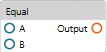
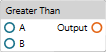
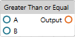
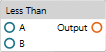
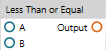
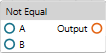
blocks are logical operators that perform mathematical comparison operations using numerical input values. The output is presented as a Boolean value.
The following blocks are available:
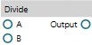
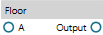
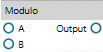
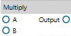
Blocks
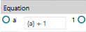
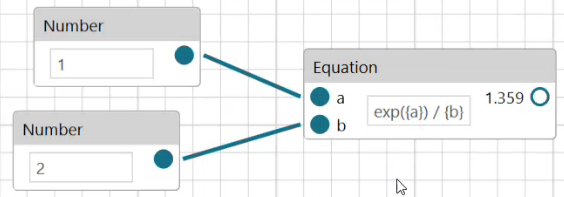
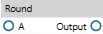
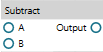
blocks are logical operators that perform mathematical operations using numerical input values and presenting numerical output values.
The following blocks are available:
Boolean Block
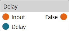
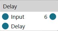
Run the command to add a block. It allows you to add a delay time (in s) defined with the Delay input after the input is received before the Boolean output is set.
If the Delay input is not connected, it is by default set to 1 s.
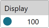
Boolean Block

Run the command to add a block. It allows you to debug and visualize the values of Boolean outputs.
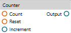
Block
|
Inputs |
Description |
|---|---|
|
Count |
When a rising edge is detected at the Count input, the Output value increases by the numerical value provided as Increment input. |
|
Reset |
When a rising edge is detected at the Reset input, the Output value is reset to 0. |
|
Increment |
Numerical input value by which the Output value is incremented when a rising edge is detected at the Count input. If the Increment input is not connected, it is interpreted as 1 by default. |
|
Outputs |
Description |
|---|---|
|
Output |
Numerical value that serves as a counter output. |
Number Block
Run the command to add a block. It allows you to add a delay time (in s) defined with the Delay input, which sets the numerical output.
Number Block
Run the command to add a block. It allows you to debug and visualize the values of numerical outputs.
Block
|
Inputs |
Description |
|---|---|
|
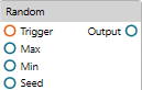
Trigger |
When a rising edge is detected at the Trigger input, a random numerical Output value is generated based on the rules defined using the Max, Min, Seed inputs. |
|
Max |
This numerical input value defines the maximum threshold of the value range for the random output value. This input value must be available to generate a random numerical Output value of type integer (, see of a block). |
|
Min |
This numerical input value defines the minimum threshold of the value range for the random output value. This input value must be available to generate a random numerical Output value of type integer (, see of a block). |
|
Seed |
This numerical input value defines the initial value for the random output value. |
|
Outputs |
Description |
|---|---|
|
Output |
Generates a random numerical value. |
of a block:
The following parameter is available in the view when a block is selected:
|
Parameter |
Description |
|---|---|
|
|
Select the type of numerical values that are generated as Output values:
Default value: |
Block
|
Inputs |
Description |
|---|---|
|
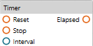
Reset |
When a rising edge is detected at the Reset input, the timer is reset. |
|
Stop |
When a rising edge is detected at the Stop input, the timer is stopped (without being reset). |
|
Interval |
This numerical input value in seconds defines the time interval for the timer. Default value: 1 s This input value is also available in the view when the block is selected. You can edit the value in the view or you can connect a numerical block to this input. Within this time interval, the output switches from FALSE to TRUE as configured with the parameter in the view. |
|
Outputs |
Description |
|---|---|
|
Elapsed |
The Boolean output switches from FALSE to TRUE within the Interval time as configured with the parameter in the view. By default, the output is 0.5 s FALSE and 0.5 s TRUE with Interval = 1 s and = 50%. |
of a block:
The following parameters are available in the view when a block is selected:
|
Parameter |
Description |
|---|---|
|
|
Time interval for the timer. Default value: 1 s Edit this value or connect a numerical block to the Interval input of the block to define a time interval within which the output switches from FALSE to TRUE as configured with the parameter. |
|
|
Configures a percentage of the time. After this percentage of the time has elapsed, the output switches from FALSE to TRUE. Default value: 50% |
|
|
By default, this option is selected and the timer is automatically reset and restarted. Clear the check box to start the timer only upon a rising edge at the Reset input. |
Example:
= 10 s
= 80%
With these settings, the Elapsed output is set to FALSE for 2 seconds and to TRUE for 8 seconds within the interval of 10 seconds.