There are two OS SKU for Box iPC. One bundled with System Monitor, another bundled with HMI Node-Red. For the OS SKU with HMI Node-Red version, there is the default password for Node-Red. User has to change the default password for Node-Red to use at the first time.
|
Step |
Action |
|---|---|
|
1 |
Power on Box iPC at the first time. |
|
2 |
Following the OS recovery procedure. |
|
Step |
Action |
|---|---|
|
1 |
Click Node-Red icon on the Windows desktop to use. |
|
2 |
At the first time, user is required to change password to start to use. |
|
3 |
The default login username is NR_account and password for Node-Red is NodeRed#0123. |
|
4 |
User must change default password to access Node-Red. If avoid to do so, will be always at change password page until really changing password accordingly to move forward. |
|
5 |
User has to enter password every time to use Node-Red password change policy: oPasswords must have at least 12 characters. oPasswords cannot contain the username. o Passwords must include the four available character types: lowercase letters, uppercase letters, numbers, and symbols. Symbols must include any one of [!"#$%&'()*+,./:;<=>?@\^_`{|}~-]. NOTE: If the password key-in is not meet above criteria, system requests again to key in password until meet criteria. |
|
Step |
Action |
|---|---|
|
1 |
Power on Box iPC every time after OS recovery procedure is completed. |
|
2 |
Following the OS recovery procedure. |
Node-Red is embedded in HMIBMI Operating System image. To up-date the Node-Red version, follow the default installation procedure on Node-Red website. https://nodered.org/docs/getting-started/installation
User has to complete the default password change before using Node-Red.
Enter IP address:1880 (port number: 1880) from remote site to use. The password is required to enter every time.
Schneider Electric Node Installation
Node-Red solution is to provide standard Node-Red pre-installed in OS image and Schneider Node which user can install from recovery USB key. Schneider Node also provides sample code and flow sample to help user to use quickly.
|
Step |
Action |
|---|---|
|
1 |
Insert USB which includes Software/SEnode_Install_packages folder. |
|
2 |
Copy SEnode_Install_packages folder to desktop. |
|
3 |
If you have installed Schneider node in your iPC before, stop Schneider Node-RED Service in Control Panel > System and Security > Administrative ToolsSystemSecurity > Services. |
|
4 |
Right-click SEnode_Install_packages/Install.bat and select Run as Administrator. |
|
5 |
After all the install processes are finished, restart the iPC. |
|
6 |
Launch Node-Red by double-click Schneider IIoT shortcut on the desktop. |
|
7 |
You see Schneider IIoT Nodes are added in Node List: 
|
|
8 |
Scroll down to see Schneider IIoT Node: 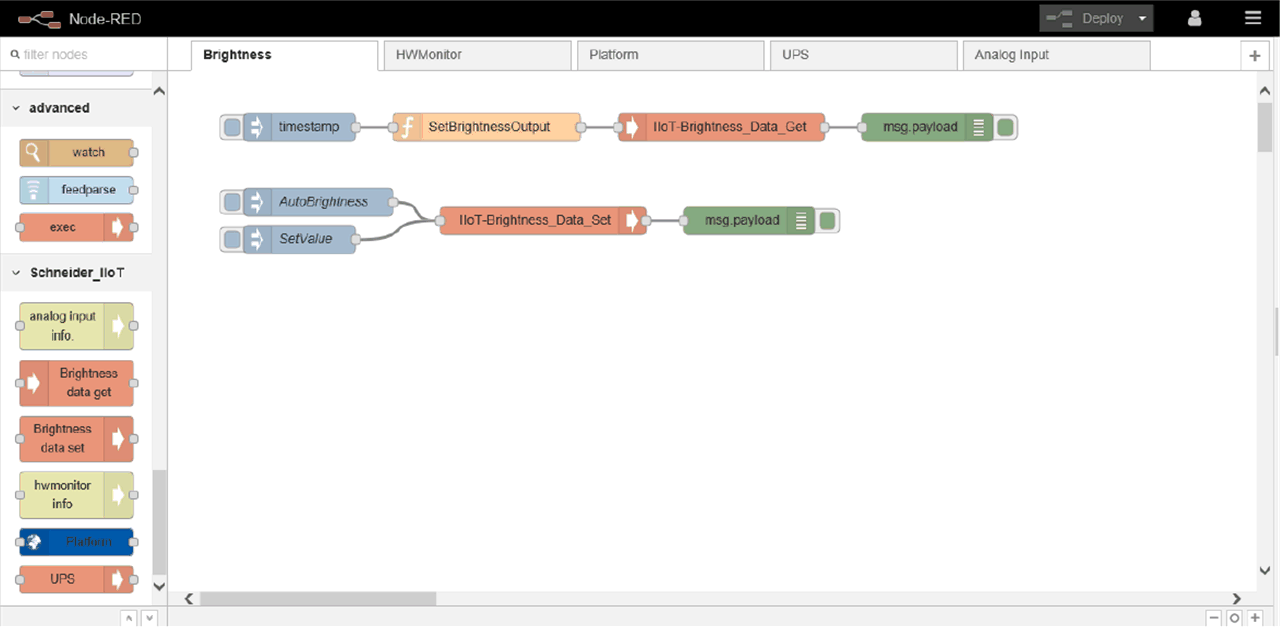
|
|
|
|
UNINTENDED EQUIPMENT OPERATION |
|
For the user who use System Monitor, do not to use Node-Red at the same time to avoid any application conflicts. Schneider-Electric do have special customized node to support hardware. Remove System Monitor and use recovery key to recover to IIoT Node-Red OS. |
|
Failure to follow these instructions can result in injury or equipment damage. |
NOTE: Although Node-Red have standard Node build in, there is no special Node that can support Schneider-Electric hardware unless you install Schneider-Electric Node. Schneider-Electric Node offers the required.
You need to create your own UI to get hardware information fromSchneider-Electric Node. You can refer to the tutorial of Node-Red dashgoard guide from the following links:
ohttp://noderedguide.com/tag/dashboard/
ohttp://noderedguide.com/tutorial-node-red-dashboards-creating-your-own-ui-widget//
This graphic is an example of dashboard to view all hardware information.

oPlatform
oUPS
oHardware Monitor
oBrightness
oAI Module
NOTE: You can simply change the value in simple code (flow sample code installer), which can be installed through USB key.
The following information can be obtained from Platform node:
|
Node Name |
Information |
Description/Value |
|---|---|---|
|
Platform |
Model name |
The information from Windows API or Supplier SNMP. |
|
BIOS version |
||
|
EC version |
||
|
OS version |
||
|
CPU name |
||
|
Disk information |
||
|
Memory available |
|
Step |
Action |
|---|---|
|
1 |
Select Platform page: 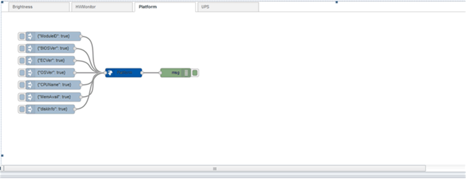
|
|
2 |
Click Deploy button to get all information from debug area: 
|
|
3 |
If you want the specific information, for example, CPU name: oClick Node Name to change OSVer in the payload column to CPUName. oClick Done to close the window of Edit inject node. 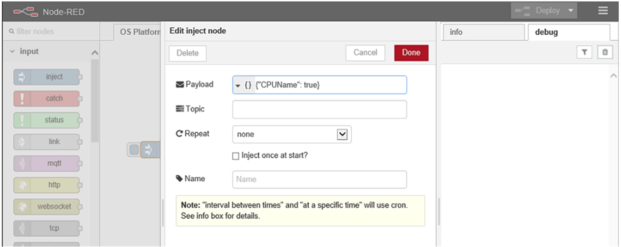
Click Deploy and then click inject button to verify the result in debug window: 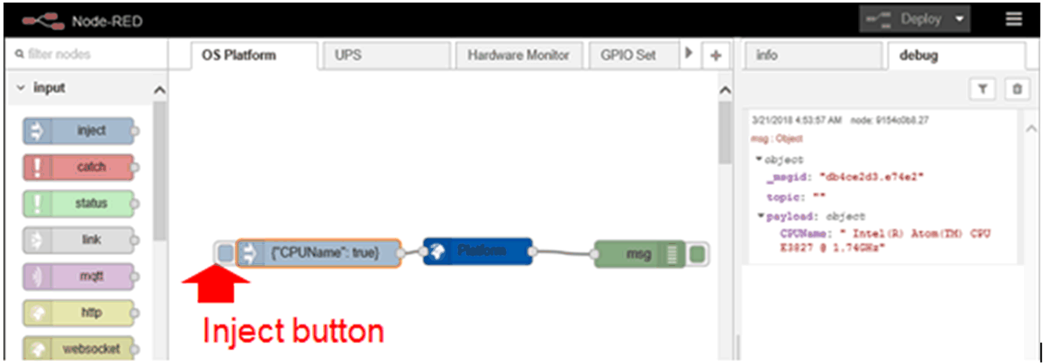
|
|
5 |
Sample flow reference. User can get all up-to-date sample flow from bellow link: C:\Program Files (x86)\Schneider Electric\IIoT\node_modules\ node-red-contrib-seplatform. |
|
Node Name |
Information |
Description/Value |
|---|---|---|
|
UPS |
Emergency Output |
oDC-IN is losted. oBattery over temperature. oBattery gauge is lost connection. oEEPROM accesses fail. oDC-IN is over voltage. oDC-Out cut-off trigger. oRestores power to IPS-AE DC-IN. |
|
Status output |
ofwversion: device firmware version. oips: the status of device. 1 is ready and 0 is not ready. odcin: the status of DC-IN. 1 is ready and 0 is not ready. obattery: the status of battery. 1 is ready and 0 is not ready. oinputlostdelay: the DC Input lost detection duration(sec). outoffdelay: the DC-OUT cut-off delay time(minutes). obatterylife: battery life (minutes) at the present rate of discharge. "65535" is battery charged. otemperature: battery. temperature (Celsius). omaxtemperature: It is the max temperature (Celsius) of battery from the system started. obatteryvoltage: It is the battery voltage (mV). ocapacity: battery capacity (%). |
|
|
Response output |
Describe the input result. |
|
Step |
Action |
|---|---|
|
1 |
Select UPS page. |
|
2 |
Double-click UPS node: 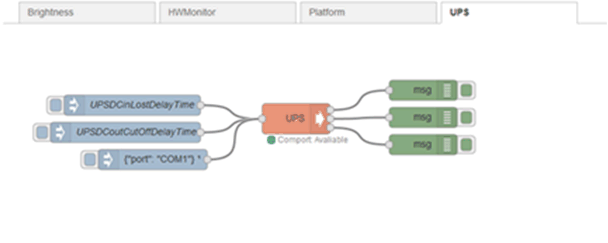
|
|
3 |
Sample code: oThe inputs must be msg.payload.UPSInputLostDelay and msg.payload.UPSCutOffDelay which are numeric. omsg.payload.UPSInputLostDelay is a number which is the DC Input Lost detection duration(sec). omsg.payload.UPSCutOffDelay is a number which is the DC-OUT cut-off delay time(minutes). oAnother input msg.payload.port is COM port name which is used to connect with UPS. 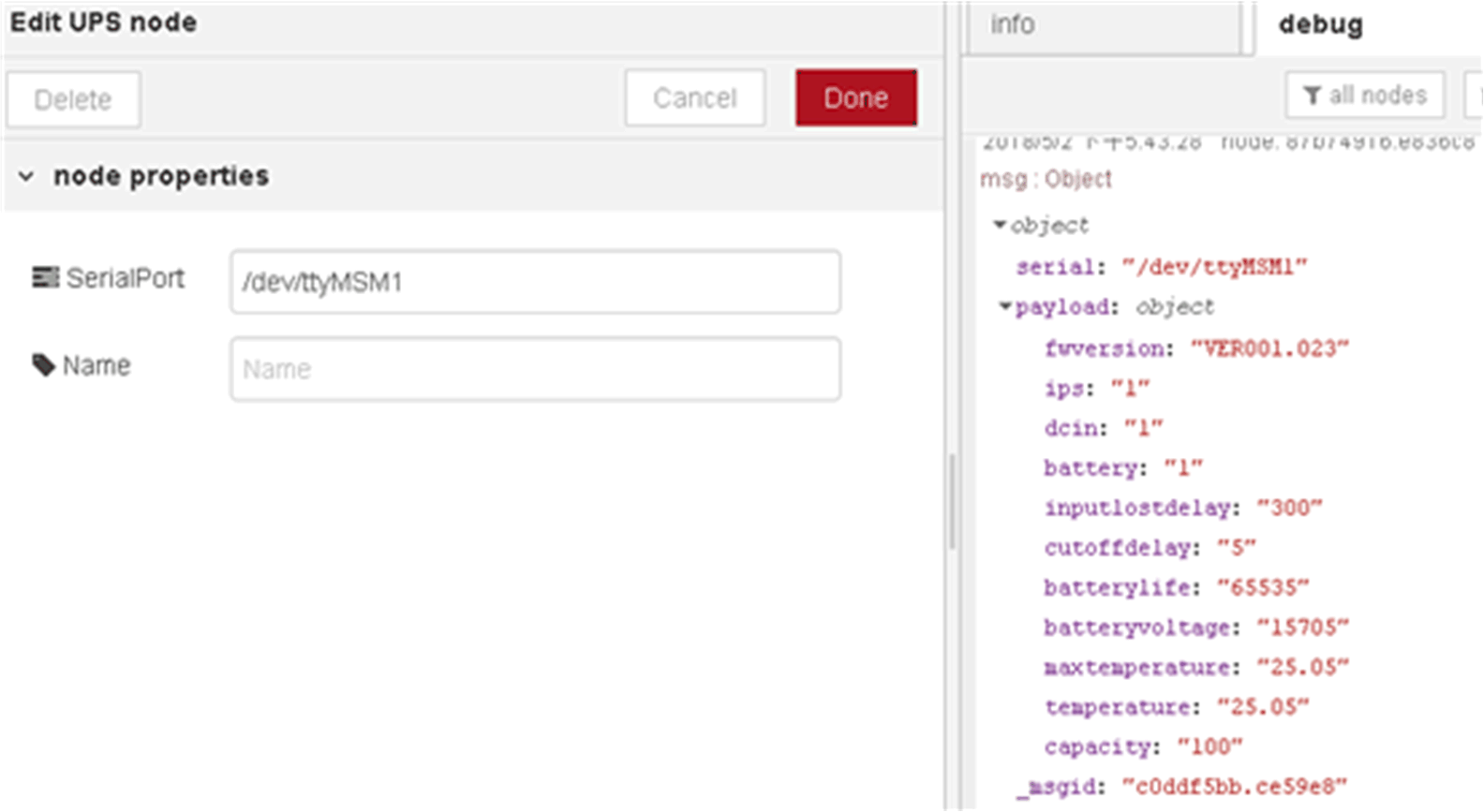
|
|
4 |
Sample code: 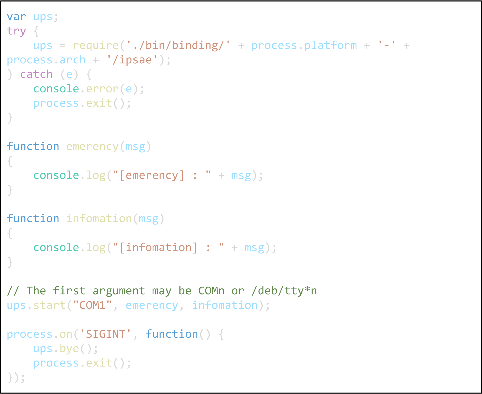
|
|
5 |
Sample code: 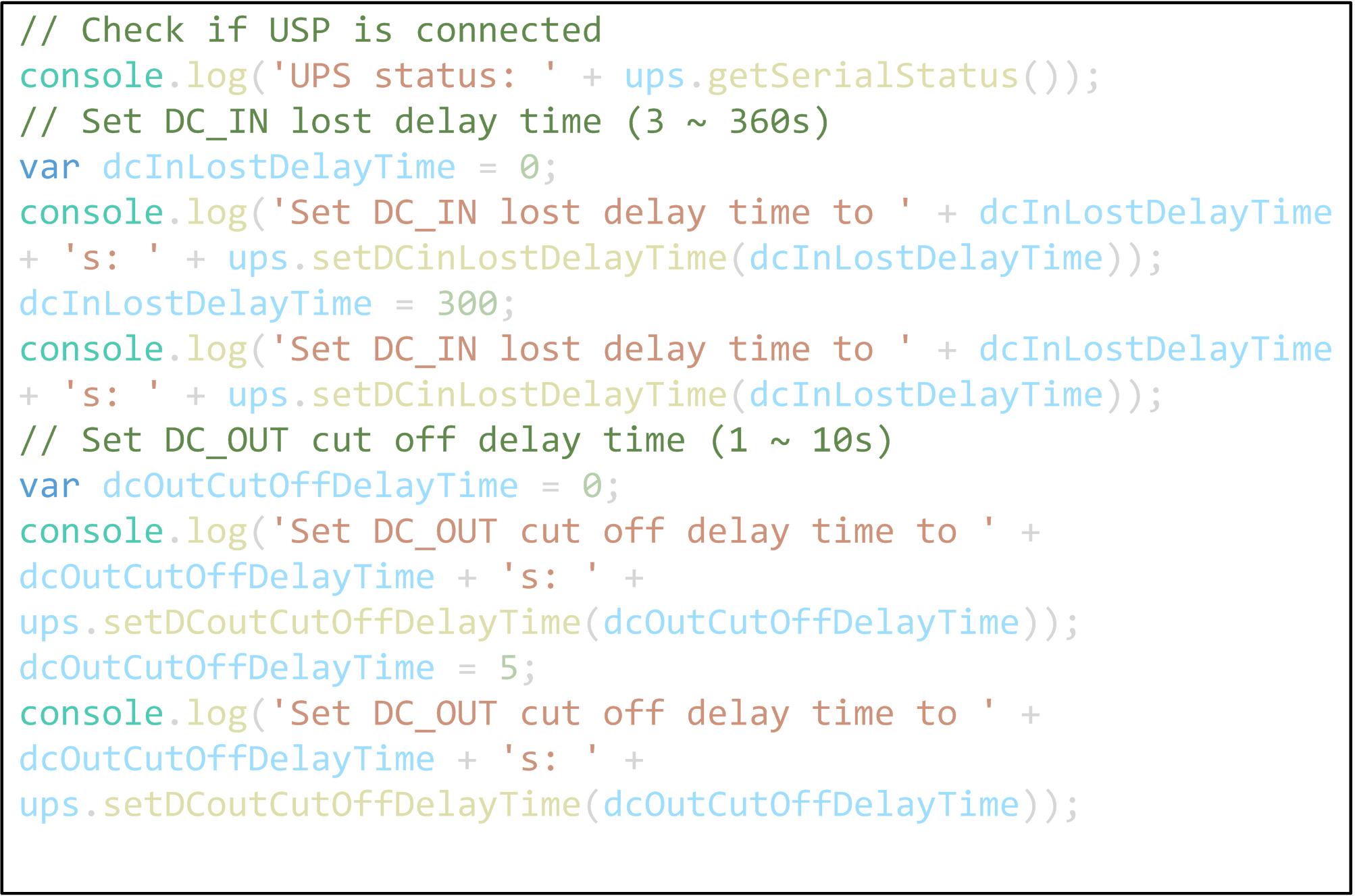
|
The following information can be obtained from Hardware Monitor node:
|
Node Name |
Information |
Description/Value |
|---|---|---|
|
Hardware Monitor |
Temperature |
All voltage information from EC. |
|
Voltage |
||
|
Current |
|
Step |
Action |
|---|---|
|
1 |
Select Hardware Monitor Page |
|
2 |
Click Deploy button to get all information from debug area: 
|
|
3 |
Click Deploy button to get all information from debug area: 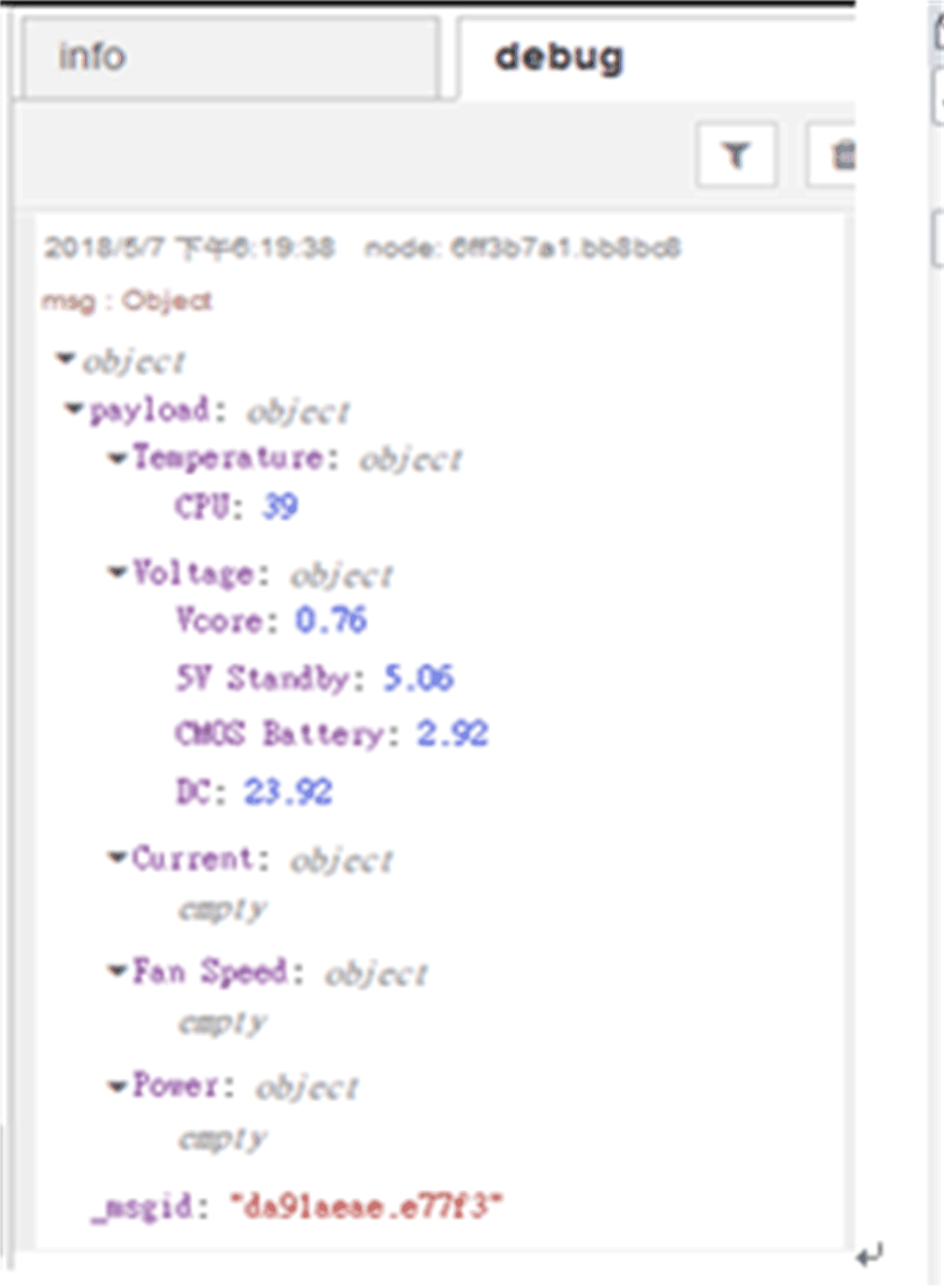
|
|
4 |
If you want the specific information, for example, Voltage: oClick hwmonitor info node to change all in the topic column to Voltage. oClick Done to close the window of Edit ihwmonitor info node. oClick Deploy and then click inject button to verify the result in debug window. 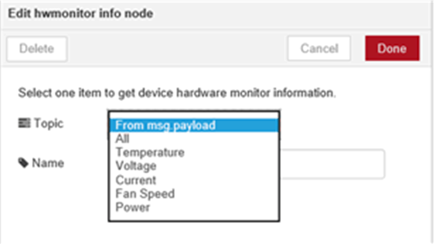
|
|
5 |
Sample flow reference. User can get all up-to-date sample flow from bellow link: /usr/lib/node_modules/node-red-contrib-selmsensor. |
|
Node Name |
Information |
Description/Value |
|---|---|---|
|
Brightness Get |
Mini |
Minimum value of brightness. |
|
Max |
Maximum value of brightness. |
|
|
Value |
Current value of brightness. |
|
|
Auto |
Auto brightness status of brightness. [0: manual, 1: auto]. |
|
Step |
Action |
|---|---|
|
1 |
Select Brighness Get Page |
|
2 |
Double-click SetBrightnessOutput Node 
|
|
3 |
Edit Node to change the setting: oMin: Minimum value of brightness oOutput (default), type the sentence of Min: true, oNo output, remove the sentence of Min: true, oMax: Maximum value of brightness oOutput (default), type the sentence of Max: true, oNo output, remove the sentence of Max: true, oValue: Current value of brightness oOutput (default), type the sentence of Value: true, oNo output, remove the sentence of Value: true, oAuto: Auto brightness status of brightness oOutput (default), type the sentence of Auto: true, oNo output, remove the sentence of Auto: true, 
|
|
4 |
Sample flow reference. User can get all up-to-date sample flow from bellow link: C:\Program Files (x86)\Schneider Electric\IIoT\node_modules\node-red-contrib-sebrightness. |
|
Node Name |
Information |
Description/Value |
|---|---|---|
|
Brightness Set |
Payload |
Set current brightness value to specified value. |
|
Set auto brightness. |
|
Step |
Action |
|---|---|
|
1 |
Select Brighness Set Page |
|
2 |
Double-click AutoBrightness Node 
|
|
3 |
You can configure the payload True or False 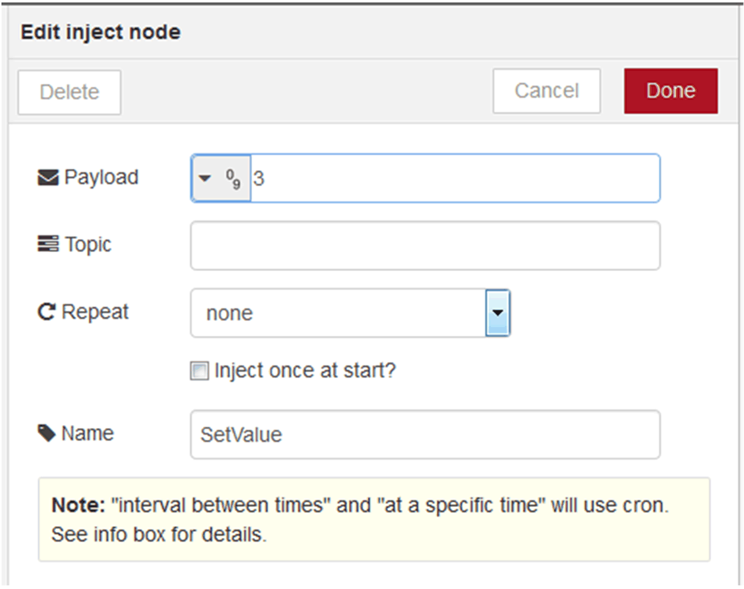
|
|
4 |
Sample flow reference. User can get all up-to-date sample flow from bellow link: C:\Program Files (x86)\Schneider Electric\IIoT\node_modules\node-red-contrib-sebrightness. |
|
Node Name |
Information |
Description/Value |
|---|---|---|
|
AI Module |
Get COM port name |
COM port name (used by this AI device). |
|
Get AI device name |
AI device name. |
|
|
Get AI firmware version |
AI firmware version. |
|
|
Get AI channel number |
AI channel number. |
|
|
Get AI value range |
AI value range. |
|
|
Set AI value range |
AI value range setting. |
|
|
Get AI value |
AI value. |
You can create your own analog input module flow or you can select the Analog Input tab to get default analog input sample flow and the sample flow is as below:
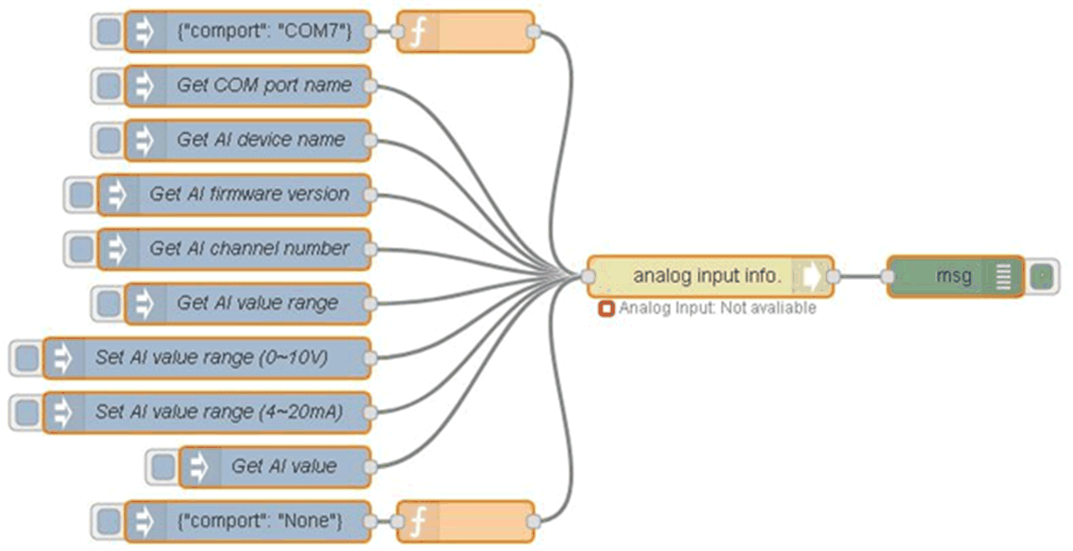
|
Step |
Action |
|---|---|
|
1 |
Select AI Module page. |
|
2 |
Edit Node to change the setting: 
|
|
3 |
At first, COM port path setting is required to make analog input module connect to host. The other functions cannot be used before finishing analog input module connection step. Set a COM port item in an analog input info node. (COMx: X = number, for example, COM7, COM number depends on the host.) 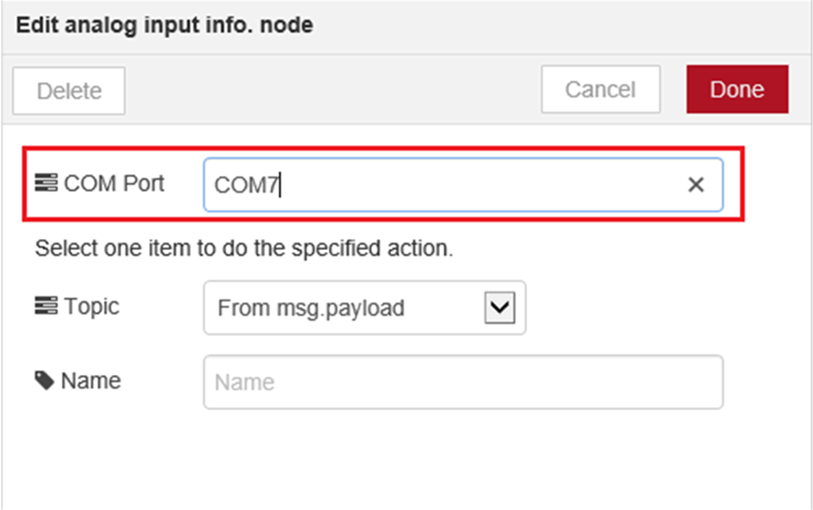
NOTE: It can also be set by Input {"comport": "COMx"} to analog input info. node. (COMx: x=number, for example, COM7, COM number depends on the host.) For example, if you want to set COM7, set msg.payload to {"comport": "COM7"} and send this message to this node. 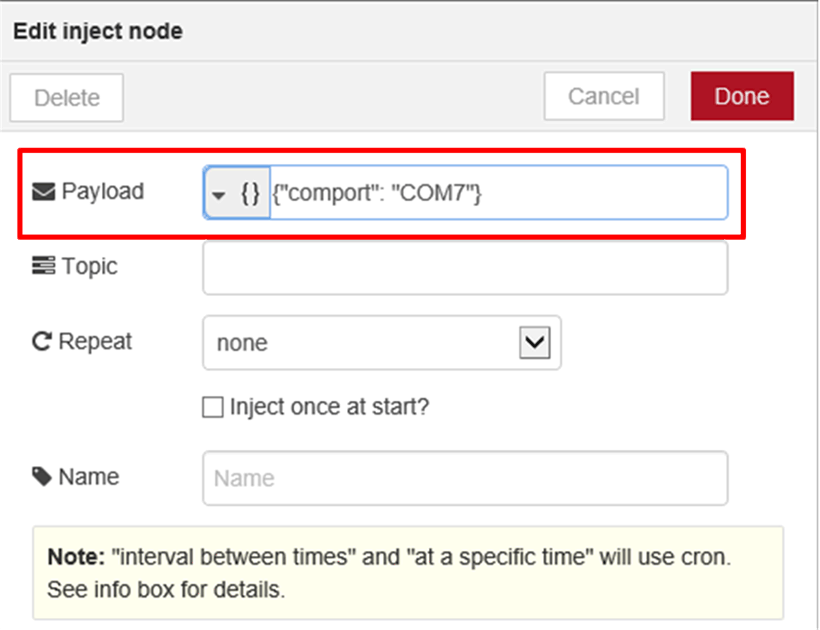
|
|
4 |
Select an item which you want to do in analog input info. node from Topic list. 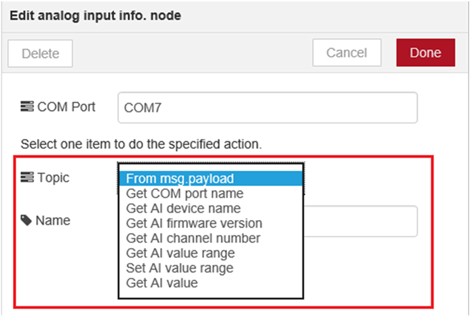
|
|
5 |
In analog input info node, select Get AI value from Topic list and set Channel Index field. NOTE: f you want to target all the channels, you can set -1 in Channel Index field. 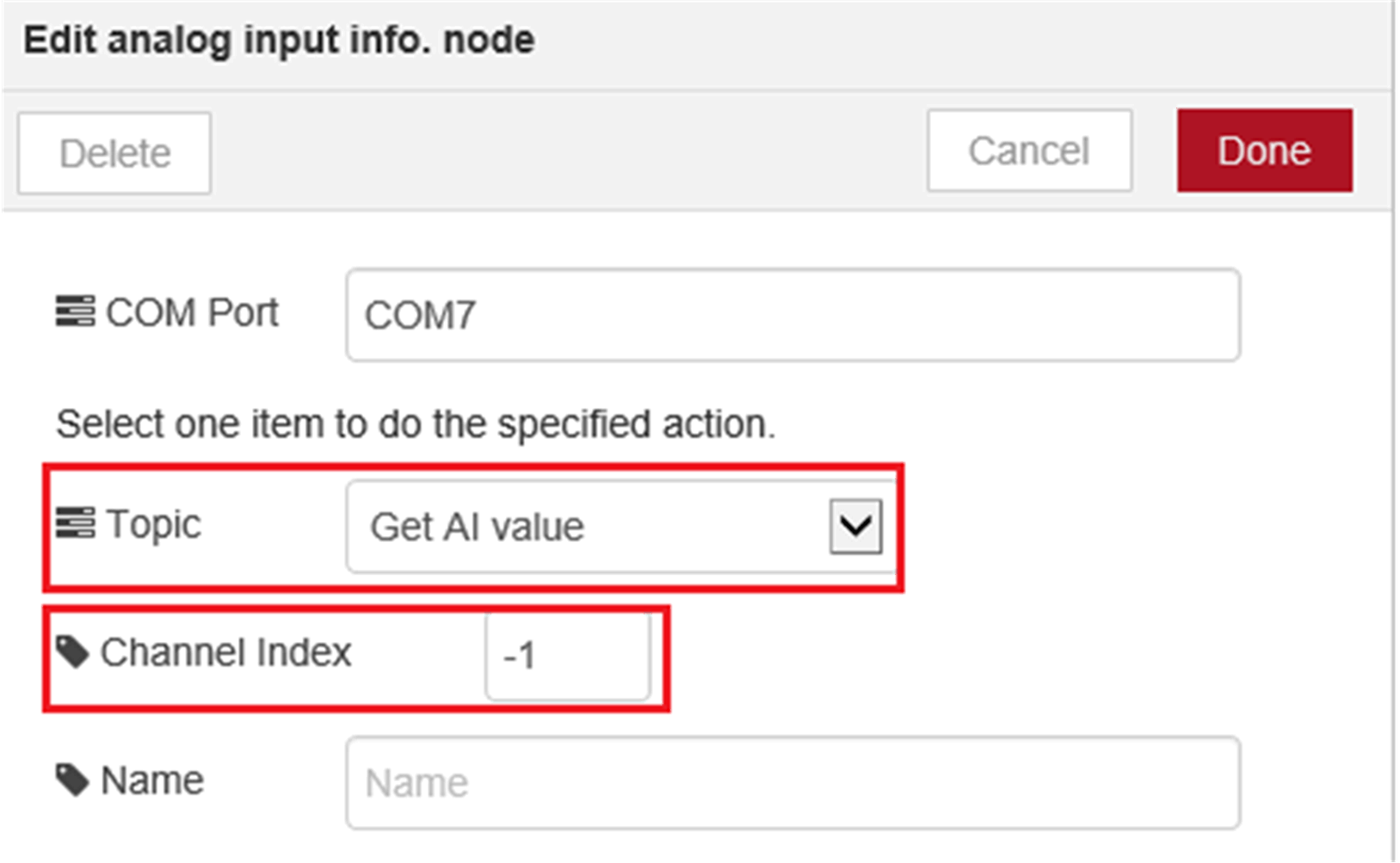
NOTE: It can also be set by Input {"attribute name": true} in msg.payload to analog input info. node. For example, if you want to get analog input value, set msg.payload to {"Get AI value": true, "chIdx": -1} and send this message to analog input info. node. If you want to target all the channels, you can set "chIdx": -1. If you want to target channel 2, you can set "chIdx": 2. 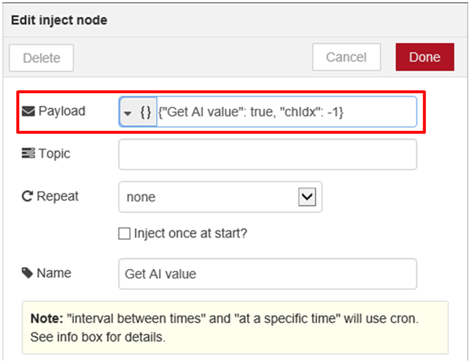
|
|
6 |
If you do not need analog input module, you can set input {"comport": "None"} to disconnect the communication between host and analog input module. Disconnected step will finish after node status changes from connected to disconnected. 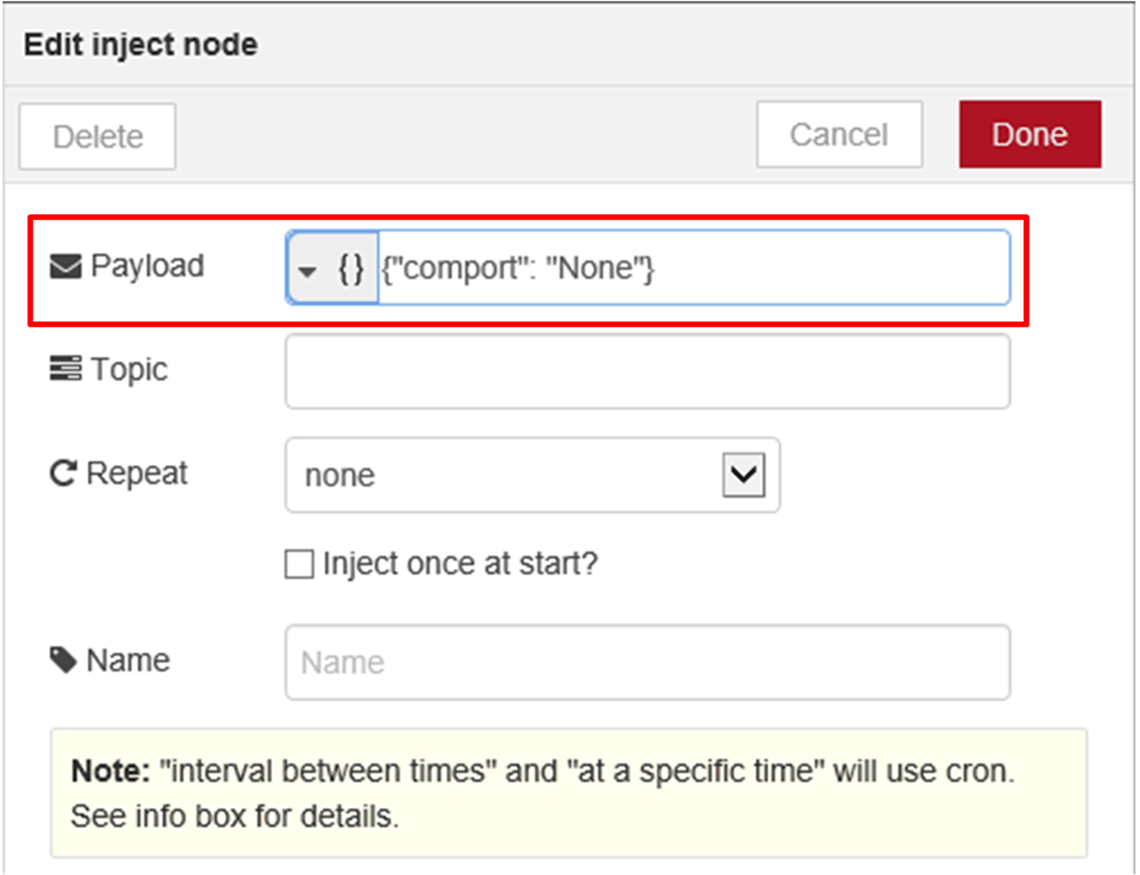
|
|
7 |
Sample flow reference. User can get all up-to-date sample flow from bellow link: C:\Program Files (x86)\Schneider Electric\IIoT\node_modules\ node-red-contrib-seai. |