Box iPC Universal and Performance (HMIBMU/HMIBMP) Description
During operation, the surface temperature of the heat sink may exceed 70 °C (158 °F).
|
|
|
RISK OF BURNS |
|
Do not touch the surface of the heat sink during operation. |
|
Failure to follow these instructions can result in death, serious injury, or equipment damage. |
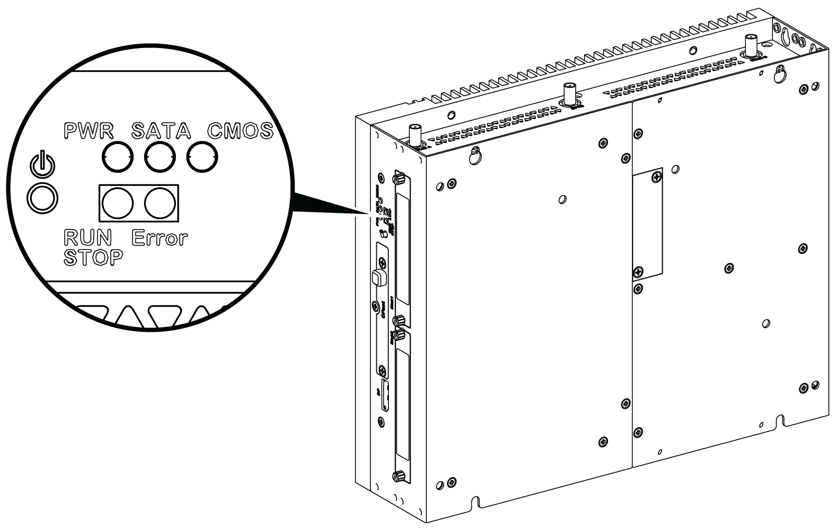
Power ON/OFF button and LEDs
The table describes the meaning of the status indicators:
|
Marking |
LED |
Color |
State |
Meaning |
|---|---|---|---|---|
|
PWR |
Power |
Green |
On |
Active (user operates Windows) (State 0). |
|
Green |
Flashing |
Sleep (State 3). |
||
|
Orange |
On |
Hibernate (State 4/State 5). |
||
|
SATA |
SATA |
Green |
Off |
No storage data transmission. |
|
On |
Storage data transmission. |
|||
|
CMOS |
Battery |
Orange |
On |
RTC voltage < 2.65 Vdc. |
|
Off |
RTC voltage > 2.65 Vdc. |
|||
|
Programmable LED for optional control software |
||||
|
RUN/STOP |
RUN/STOP from control software |
Red |
Off |
Stop |
|
Green |
On |
Run |
||
|
ERR |
Error from control software |
Red |
Off |
Control software has no error. |
|
On |
Control software has an error. |
|||
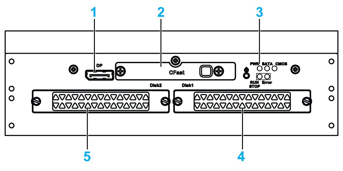
1 DisplayPort 2
2 Slide-in CFast slot
3 LEDs and power/reset button
4 HDD/SSD 1 (hot swap and can be RAID configuration)
5 HDD/SSD 2 (hot swap and can be RAID configuration)
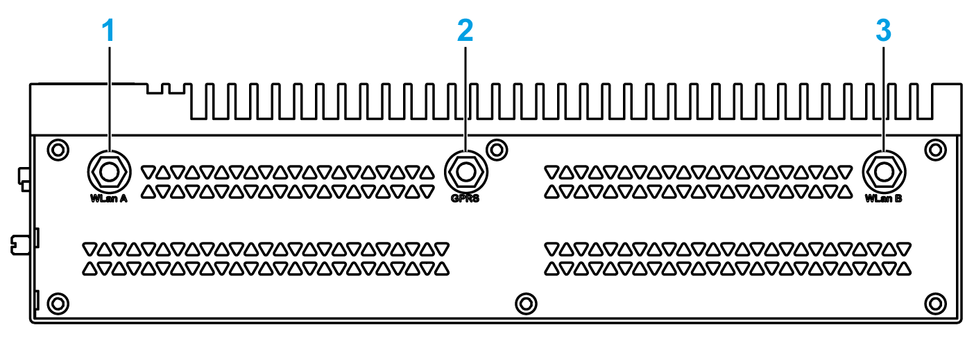
1 SMA connector for the WLan external antenna
2 SMA connector for the GPRS/4G external antenna
3 SMA connector for the WLan external antenna
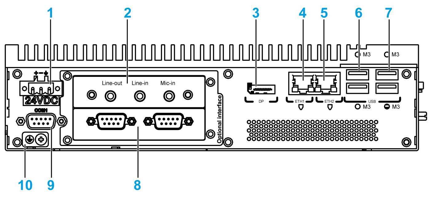
1 DC power connector
2 Optional interface 1
3 DisplayPort 1
4 ETH1 (10/100/1000 Mb/s) IEEE1588
5 ETH2 (10/100/1000 Mb/s) IEEE1588
6 USB1 and USB2 (USB 3.0)
7 USB3 and USB4 (USB 2.0)
8 Optional interface 2
9 COM1 port RS-232, RS-422/485 (isolated)
10 Ground connection pin
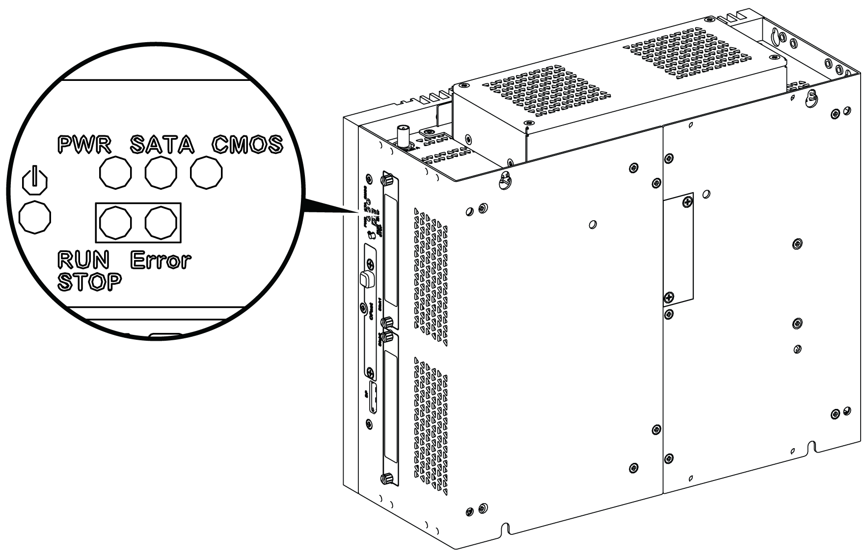
Power ON/OFF button and LEDs
The table describes the meaning of the status indicators:
|
Marking |
LED |
Color |
State |
Meaning |
|---|---|---|---|---|
|
PWR |
Power |
Green |
On |
Active (user operates Windows) (State 0). |
|
Green |
Flashing |
Sleep (State 3). |
||
|
Orange |
On |
Hibernate (State 4/State 5). |
||
|
SATA |
SATA |
Green |
Off |
No storage data transmission. |
|
On |
Storage data transmission. |
|||
|
CMOS |
Battery |
Orange |
On |
RTC voltage < 2.65 Vdc. |
|
Off |
RTC voltage > 2.65 Vdc. |
|||
|
Programmable LED for optional control software |
||||
|
RUN/STOP |
RUN/STOP from control software |
Red |
Off |
Stop |
|
Green |
On |
Run |
||
|
ERR |
Error from control software |
Red |
Off |
Control software has no error. |
|
On |
Control software has an error. |
|||
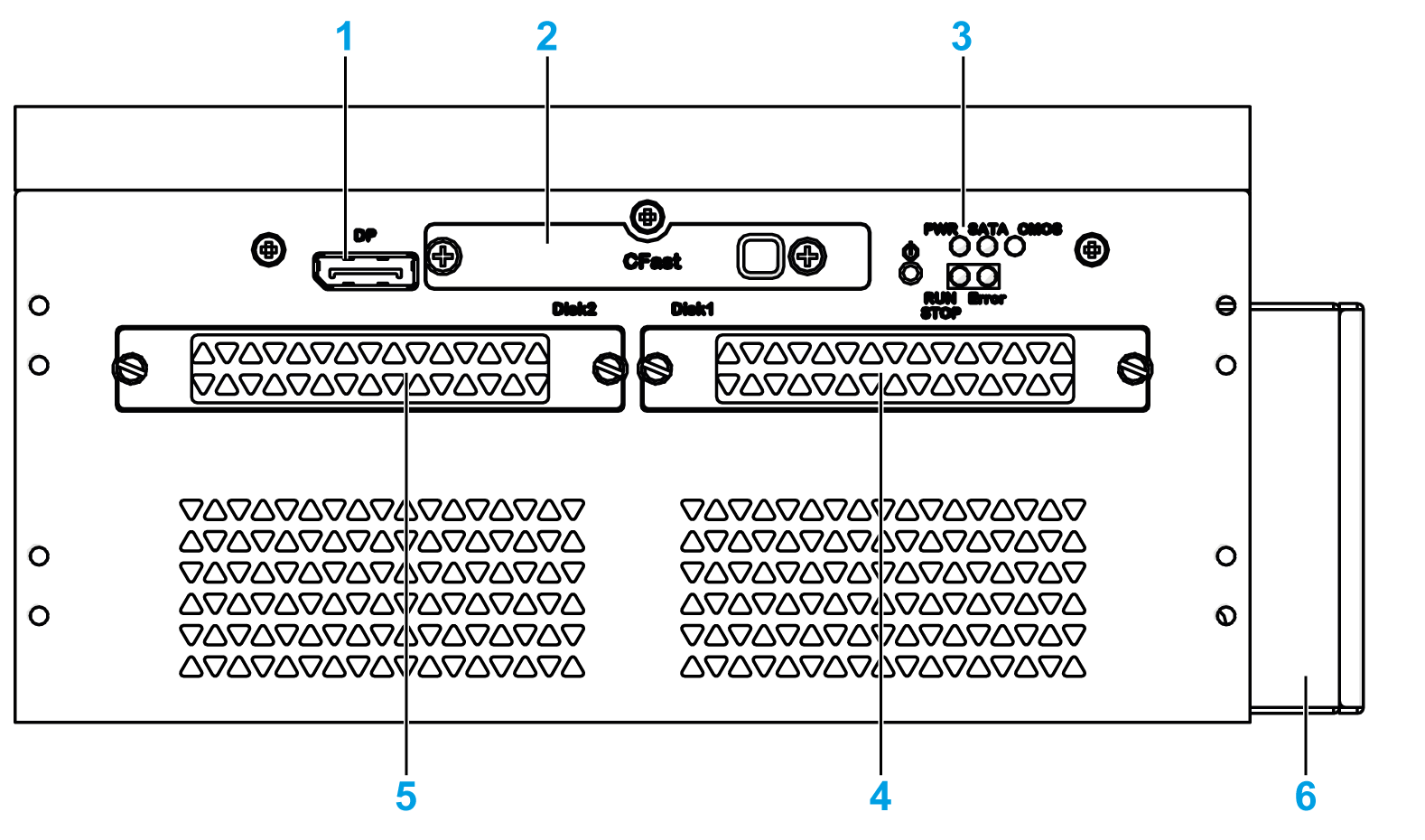
1 DisplayPort 2
2 Slide-in CFast slot
3 LEDs and power/reset button
4 HDD/SSD 1 (hot swap and can be RAID configuration)
5 HDD/SSD 2 (hot swap and can be RAID configuration)
6 Fan
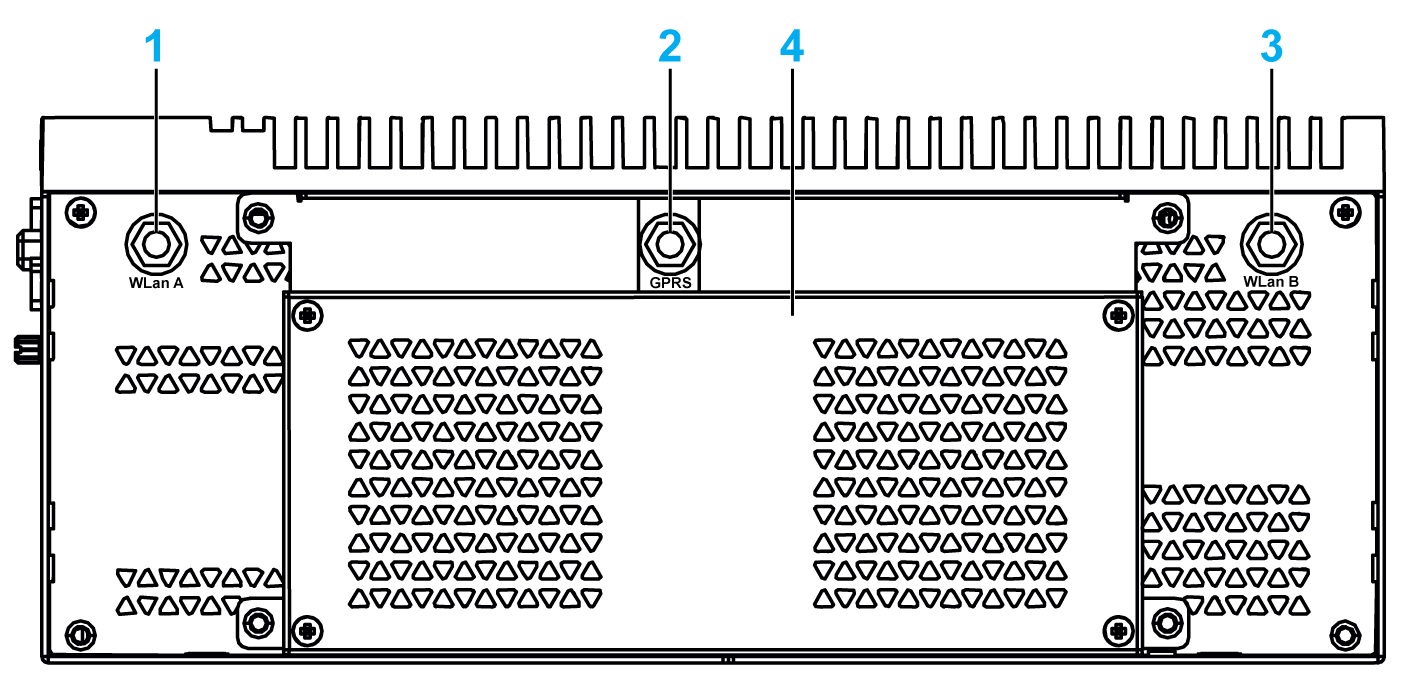
1 SMA connector for the WLan external antenna
2 SMA connector for the GPRS/4G external antenna
3 SMA connector for the WLan external antenna
4 Fan
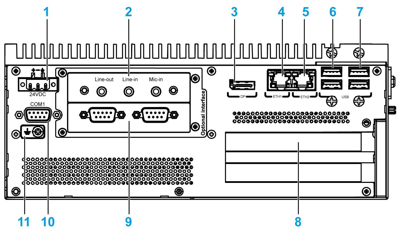
1 DC power connector
2 Optional interface 1
3 DisplayPort 1
4 ETH1 (10/100/1000 Mb/s) IEEE1588
5 ETH2 (10/100/1000 Mb/s) IEEE1588
6 USB1 and USB2 (USB 3.0)
7 USB3 and USB4 (USB 2.0)
8 PCI or PCIe (peripheral component interconnect express) slots
9 Optional interface 2
10 COM1 port RS-232, RS-422/485 (isolated)
11 Ground connection pin
Box iPC and Display Description
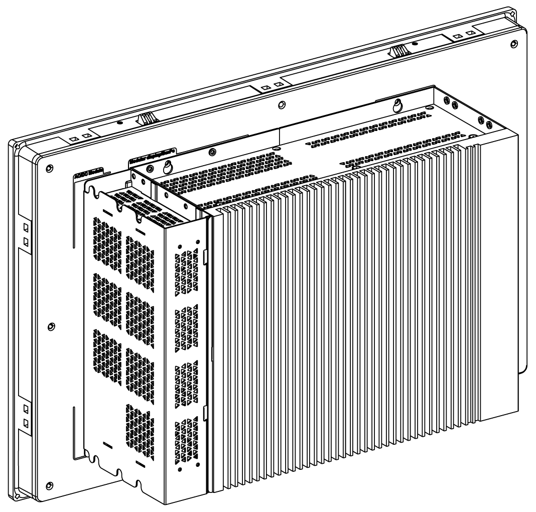
NOTE:
oThe Box iPC (HMIBMU/HMIBMP) can support two DisplayPort. When the Box iPC is mounted with the display, the DisplayPort 2 is not functional.
oAfter DisplayPort cable is connected, Operating System must be rebooted.
oFor connecting the Box iPC to a display with DVI interface, use an active DP to DVI cable: HMIYADDPDVI11 (see in accessories).
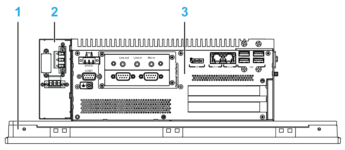
1 Display
2 Optional AC power supply module (HMIYMMAC1)
3 Box iPC