Display Adapter Description and Configuration
The display can be mounted remotely from the Box iPC, using the Display Adapter.
The Display Adapter can be connected to any PC with USB cable for touch screen and DisplayPort cable for video (HMIYCABUSB51 / HMIYCABDP51 maximum distance of 5 m (16.4 ft)).
When equipped with a Receiver module and Transmitter module, up to 4 Display Adapters can be connected to one Box iPC equipped with Optional Interface for the RJ45 connector for CAT5e/CAT6 Ethernet cable. In this configuration, the single RJ45 connector for CAT5e/CAT6 cable supports both touch screens and video signal for a maximum distance of 100 m between devices, a maximum of 400 m total for 4 displays.
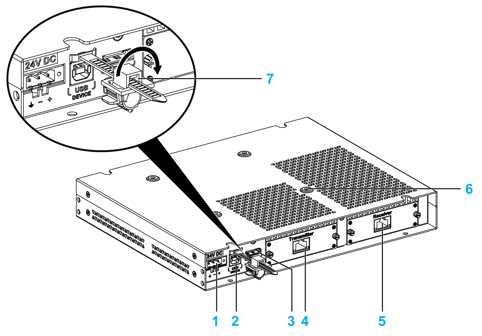
1 DC power supply connection
2 USB port type B (USB 2.0 for touch screen OUT)
3 DisplayPort (IN)
4 Transmitter module (HMIYDATR11) with RJ45 port
5 Receiver module (HMIYDARE11) with RJ45 port
6 Mounting holes for the VESA
7 USB locker
Local Display Configuration with DisplayPort Connection (Maximum Distance: 5 m)
|
Step |
Action |
|---|---|
|
1 |
Connect the Display Adapter to host PC using DP cable: 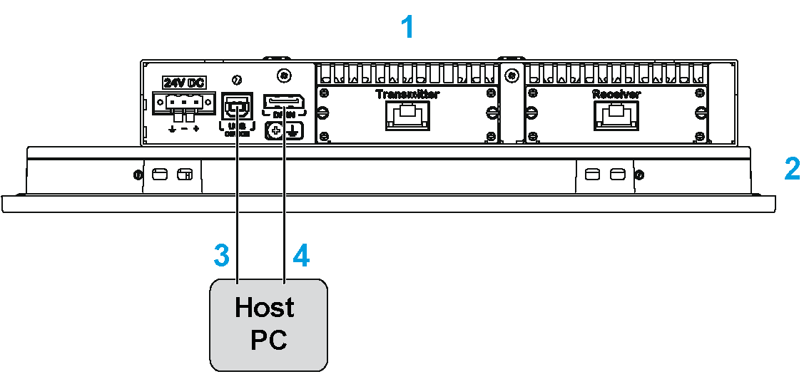
1 Display Adapter 2 Display 3 USB cable 5 m (HMIYCABUSB51) 4 DP to DP cable 5 m (HMIYCABDP51) |
|
2 |
Install the touch driver from either the recovery media of box or from the DVD of the Display Adapter. |
|
3 |
Connect the Display Adapter to a host PC via a USB cable to use Touch function. |
NOTE:
oThe displays W12”, W15”, W19”, and W22” have multi-touch screen.
oThe reset button on the display 4:3 12” and 4:3 15” is only for the Display Adapter reset. It cannot reset the host PC.
oThe Display Adapter with display does not support brightness control. The brightness is always 100%.
oOnce the DisplayPort cable is connected, the Operating System must be rebooted.
oFor operation with 100...240 Vac in hazardous location, the AC power supply module (HMIYMMAC1) must be mounted.
oThe length of the DP and USB cables is limited up to 5 m (16.40 ft).
Remote Display Configuration with Receiver module and Transmitter module (Maximum Distance: 4 x 100 m)
The Receiver module and Transmitter module can be used to connect multiple displays in a daisy chain manner. The Display Adapters are connected by Ethernet cables (type CAT5e/CAT6) with a maximum distance of 100 meters between two devices.
The Box iPC can support data transfer with four displays that have a Display Adapter, so with a maximum distance up to 4 x 100 m = 400 m (437 yd). The four displays are clone displays.
|
Step |
Action |
|---|---|
|
1 |
Install the mini PCIe card and the mini PCIe to Display Adapter Interface in the Box iPC. |
|
2 |
Connect the Display Adapter and all the Transmitter module / Receiver module on remote displays using Ethernet cables (type CAT5e/CAT6): 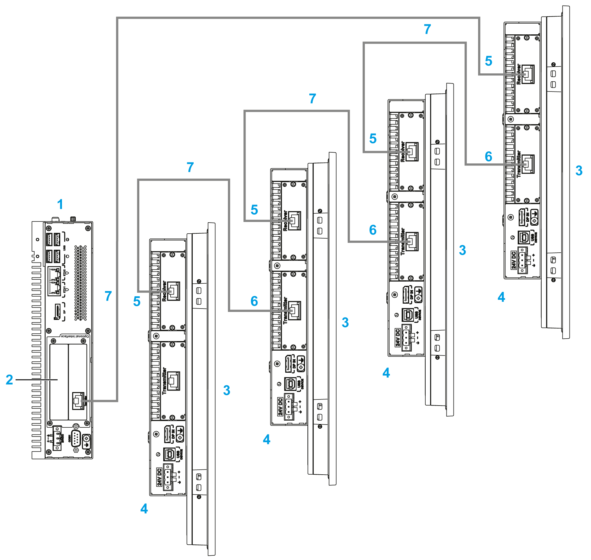
1 Box iPC 2 mini PCIe to Display Adapter Interface 3 Display 4 Display Adapter 5 Receiver module 6 Transmitter module 7 Ethernet cables (type CAT5e/CAT6) NOTE: Connect remote display one by one during installation. |
|
3 |
Power on system into the windows. Check that the BIOS Graphic of the Box iPC is set to IGFX. NOTE: oA screen directly connected to the box is required for commission. oDo not connect all remote displays before powering into Windows. Connect the remote display one by one after setting well (step 1...5), then connect to next remote display (repeat step 1...5) until all sets. |
|
4 |
Install the driver from the recovery USB memory key. |
|
5 |
Reboot the system to get correct setting. |
NOTE:
About remote displays configuration (except resolution settings):
oThe length of the Ethernet cable is limited up to 100 m to the next Display Adapter.A maximum of four Display Adapters can be connected via RJ45 on the same PC.
oA maximum one mini PCIe to Display Adapter Interface (HMIYMINDP1), per Box iPC.
oTo set up the mini PCIe to Display Adapter Interface (HMIYMINDP1), you need a display or a third-party monitor on host PC to install the driver. Once the remote display configurations are ready, the display on the host PC can be removed if it is not used.
oA driver is required on the PC where the mini PCIe to Display Adapter Interface (HMIYMINDP1) is installed. If the driver is not pre-installed, it is available on the Schneider Electric site.
oWhen connecting the remote display to the Box iPC, be sure not to connect the cable to the Ethernet port of the Box iPC, but to the RJ45 port on the mini PCIe to Display Adapter Interface.
oThe remote display cable does not support the normal LAN HUB or switch because the signal type is different.
oThe CAT5e cable may be used for more limited length, according to environmental conditions and with a maximum screen resolution of 1920 x 1080 pixels.
oWhen the Receiver module is connected, the local connection with the host using DP and USB cables is disabled and the host PC screen is displayed. But when the Box iPC interface Receiver module cable is disconnected, it automatically switches to the host PC screen.
oThe Display Adapter must be used with a display product version 02 or above.
oThe touch panel of the display is single use at a time and need waiting until the finger comes out; then other touch panels can work (waiting time 100 ms).
oTouch Disable function on remote displays only supports normal operating state. When the host PC is rebooting, turns off, in S3 mode (lower power state) or S4 mode (hibernate state); the USB device is reorganized and its system cannot get which remote touch is in Touch Disable mode.
oThe reset button on display 4:3 12” and 4:3 15” is only for the Display Adapter reset. It cannot reset the host PC.
oThe Display Adapter with display does not support brightness control. The brightness is always 100%.
oWith the remote display cable (100 m), the touch-beep sound cannot be heard from the touch-panel side because the buzzer is on the Box iPC side.
oThe display only supports the 2D function when the remote Display Adapter is used as the main display.
oWhen using four Display Adapters, you cannot use the front USB port on the displays (4:3 12” or 4:3 15”).
oWith remote display module, the screen rotation is not available with Windows 7 and WES7.
oWindows Media Player is not recommended to play video on remote displays because of mini PCIe interface graphic card performance limitation. VLC player or other professional video application is recommended instead of.
oThe host display on Windows 7 cannot scale to the extended display because the mini PCIe to Display Adapter Interface card driver does not support the extension mode.
To Manage the Display Resolution in the Remote Display Configuration
Box iPC uses the Extended Display Identification Data (EDID) information, with default setting 1366 x 768 pixel resolution when the mini PCIe interface has been installed. On the first connection, the displays connected via the Transmitter module and the Receiver module display 1366 x 768 pixels whatever the display sizes are:
oThe host PC automatically detects the first remote display resolution, during host PC restart, shut-down, S3 mode (lower power state) or S4 mode (hibernation state). Make sure that the first remote display is connected and power on. Otherwise the host PC is not able to detect the first remote display resolution and the resolution setting is not remotely correct.
oAll remote displays must have same resolution. 4:3 and 16:9 resolutions cannot be mixed on the remote displays.
Default resolution setting:
|
4:3 12”/4:3 15” |
W12” |
W15”/W19” |
W22” |
|---|---|---|---|
|
1024 x 768 pixels |
1280 x 800 pixels |
1366 x 768 pixels |
1920 x 1080 pixels |
Display with No Signal Message
When the host PC is turned off, or one of the display of the daisy chain is turned off or disconnected, the next other displays in the daisy chain get NO SIGNAL message on their screens. When the NO SIGNAL message appears, the remote display has no function (no touch and no display):
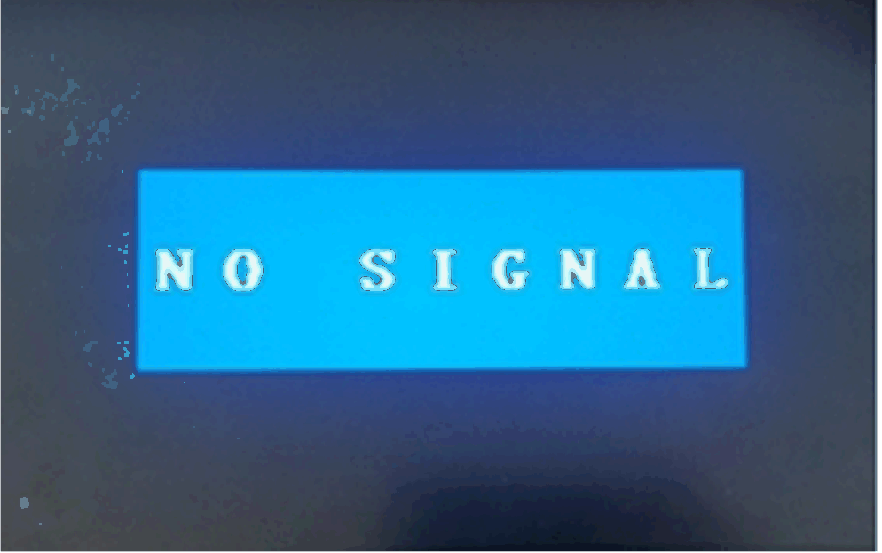
This is an informative note to you to check:
oIf the Ethernet cables on remote displays are disconnected, check, and reconnect. After one minute, the remote displays resume their normal operation.
oIf the host PC gets to S3 (lower power state) or S4 mode (power hibernation state), click any screen of the remote display to reactive the PC and resume normal operation.
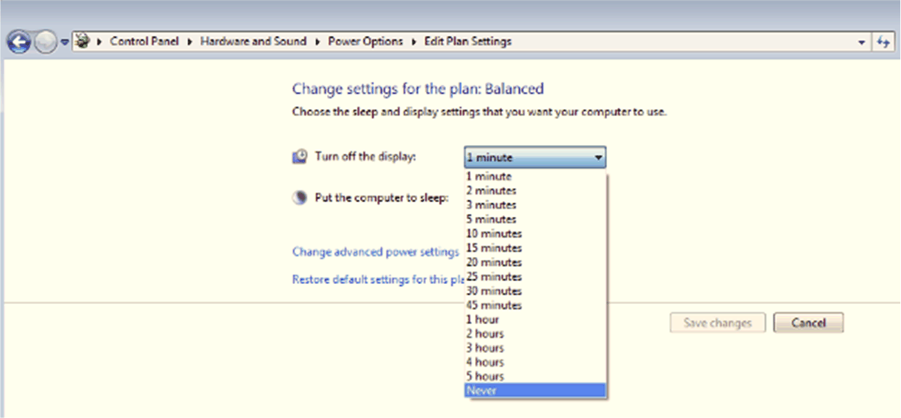
oIf the host PC set the Turn off the Display mode in Power Options > Edit Plan Setting, click any screen in the remote display to wake up the PC and get back to normal status.
You can set the host PC in S3 or S4 mode if necessary:
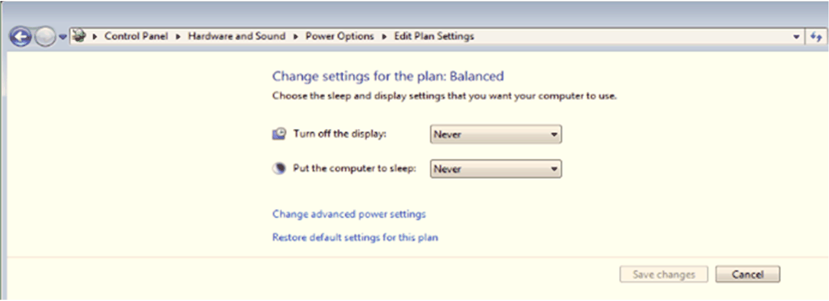
Recommend that default setting is Never to avoid the remote display from changing to the NO SIGNAL message too often and impact the remote display operation:
