Safety Module Parameters and Process Data Items
The parameters of the safety-related modules can be set in the safety-related Device Parameterization Editor. This editor is part of the EcoStruxure Machine Expert - Safety 'Devices' window.
To edit the parameters of a safety-related module, left-click the respective tree node in the 'Devices' window. Its parameters are then visible in the grid tabs on the right.
Further Information
For further information refer to the "Device Parameterization" topic of the EcoStruxure Machine Expert - Safety documentation.
The process data items are listed under the module node in the device tree. These signals can either be read or written by the application (depending on the signal type). When dragging a process data item from the 'Devices' window into the safety-related code, a global variable is created.
Further Information
Also refer to the topic "Connecting/Disconnecting Process Data Items and Global I/O Variables" in the EcoStruxure Machine Expert - Safety online help.
Further Information
Refer to the respective device manual for further safety-related information and parameter-/module-specific hazard messages.
Safety-Related Products of the Safety Logic Controller system
The Safety Logic Controller system is comprised of the following safety-related products:
|
Module Type |
Reference |
|
Safety Logic Controller, SLC 100 Sercos III, 24 VDC |
|
|
Safety Logic Controller, SLC 200 Sercos III, 24 VDC |
|
|
Safety-related Module 2DI 24 VDC |
|
|
Safety-related Module 4DI 24 VDC |
|
|
Safety-related Module 20DI 24 VDC |
|
|
Safety-related Module 2DO 24 VDC, 0.5 A |
|
|
Safety-related Module 2DO 24 VDC, 2 A |
|
|
Safety-related Module 2 relay outputs 24 VDC, 6 A |
|
|
Safety-related Module 4DO 24 VDC, 0.5 A |
|
|
Safety-related Module 4DO 24 VDC, 2 A |
|
|
Safety-related Module 6DO 24 VDC, 0.2 A |
|
|
Safety-related Module 2DI (2 pulse output), 2DO 24 VDC, 6 A |
|
|
Safety-related Module 6DI (6 pulse output), 6DO 24 VDC, 0.5 A |
|
|
IP67 Block, 8DI, 4DO, 2 A |
|
|
Safety-related Module 8DI (2 standard DI, 2 pulse output), 2standard DO 24 VDC, 12 A, M12 device interface |
|
|
Safety-related Module 4AI (2x2 current input, 4 to 20 mA, 24 bit converter resolution) |
|
|
Safety-related Temperature Module (2x2 analog thermocouple inputs for thermoelements of the types J, K, N, S, R, C, T and 1x2 safety-related analog PT100/PT1000 input, 24 bit converter resolution) |
|
|
Safety-related Digital Counter Module (1 safety-related digital counter channel, max. input frequency 7 kHz, 24 VDC) |
|
|
Safety-related Power Supply Module (24 VDC, 10 A) |
|
|
Safety Module for LXM62 Drives |
|
|
Safety Module for ILM62 Drives |
|
|
TM5 Bus Base for safety-related Electronic modules, safety coded, internal I/O supply interconnected |
TM5ACBM3FS |
|
Safety-related Terminal Block, 12-pin, safety coded |
TM5ACTB52FS |
|
Memory Key 2 MB1 |
TM5ACSLCM2FS |
|
Memory Key 8 MB1 |
TM5ACSLCM8FS |
|
1 |
A memory key is required for operation of the Safety Logic Controller. For more information concerning the role of the memory key in the Safety Logic Controller system, refer to the Safety Logic Controller SLC100/200 FS - Hardware Guide. |
Only modules designated as safety-related modules are allowed to perform safety-related functions. Make certain that neither inputs nor outputs of non-interfering modules are used for safety-related inputs or outputs.
DANGER
IMPROPERLY CONFIGURED SAFETY-RELATED SYSTEM
Use only products designated as functional safety devices for use in a safety-related system.
Use only Schneider Electric authorized products in a Safety Logic Controller system.
Failure to follow these instructions can result in death, serious injury, or equipment damage.
NOTE:
The Sercos III Bus Interface, required for communication with safety-related TM5 modules, is considered a non-interfering module and does not contribute nor detract from the safety-related function of the controller. The safety support layer riding on the Sercos III communication is managed inside the safety-related modules and not in the Sercos III Bus Interface.
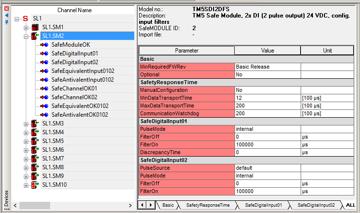
Example: Parameters and process data items of a digital input safety-related module
After selecting a module in the Devices tree on the left, the parameters are visible and can be edited in the grids on the right. The process data items (signals) of a module can be dragged into FBD/LD code worksheets thus creating a related global variable which can be read or written by the application (depending on the signal type).
