NOTE: Prog port (USB mini-B) is not active.
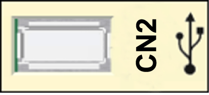
Connection CN2 USB - A
|
Pin |
Designation |
Meaning |
|---|---|---|
|
1 |
VBUS / +5V |
– |
|
2 |
D- / Data- |
Data line - |
|
3 |
D+ / Data+ |
Data line + |
|
4 |
GND / Ground |
– |
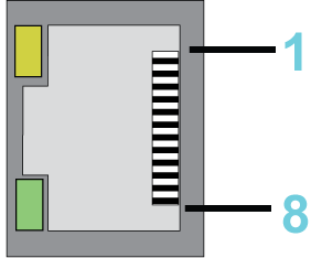
Connection CN3
|
Pin |
Designation |
|---|---|
|
1 |
D1 + (Tx+) |
|
2 |
D1- (Tx-) |
|
3 |
D2+ (Rx+) |
|
4 |
D3+ |
|
5 |
D3- |
|
6 |
D2- (Rx-) |
|
7 |
D4+ |
|
8 |
D4- |
CN3 LEDs
|
LED |
Function |
Off |
On |
Flashes |
|---|---|---|---|---|
|
Green |
State |
No connection |
Connection, no activity |
Connection and activity |
|
Yellow |
Velocity |
10 MBit |
100 MBit / 1 GBit |
– |

Connection CN4
|
Pin |
Designation |
Meaning |
|---|---|---|
|
1 |
TxD |
RS-232, transmit data |
|
2 |
RxD |
RS-232, receive data |
|
3 |
CTS |
RS-232, clear to send |
|
4 |
D1 / B |
Modbus D1, RS-485 B |
|
5 |
D0 / A |
Modbus D0, RS-485 A |
|
6 |
RTS |
RS-232, request to send |
|
7 |
– |
Reserved |
|
8 |
0 V |
Signal and power common |

Connection CN5
|
Pin |
Designation |
Meaning |
|---|---|---|
|
1 |
Tx+ |
Transmit data + |
|
2 |
Tx- |
Transmit data - |
|
3 |
Rx+ |
Receive data + |
|
4 |
– |
Reserved |
|
5 |
– |
Reserved |
|
6 |
Rx- |
Receive data - |
|
7 |
– |
Reserved |
|
8 |
– |
Reserved |
The Sercos LEDs indicate the state of the Sercos connection:
|
LED |
On |
|---|---|
|
Green |
Activity |
|
Yellow |
Connection |

Connection CN6
|
Pin |
Designation |
Meaning |
|---|---|---|
|
1 |
Tx+ |
Transmit data + |
|
2 |
Tx- |
Transmit data - |
|
3 |
Rx+ |
Receive data + |
|
4 |
– |
Reserved |
|
5 |
– |
Reserved |
|
6 |
Rx- |
Receive data - |
|
7 |
– |
Reserved |
|
8 |
– |
Reserved |
The Sercos LEDs indicate the state of theSercos connection:
|
LED |
On |
|---|---|
|
Green |
Activity |
|
Yellow |
Connection |
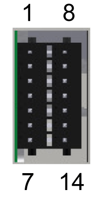
Connection CN7
|
Pin |
Designation |
Meaning |
|---|---|---|
|
1 |
DI0 |
Digital inputs |
|
2 |
DI1 |
|
|
3 |
DI2 |
|
|
4 |
DI3 |
|
|
5 |
DI4 |
|
|
6 |
DI5 |
|
|
7 |
0V1 |
Reference potential DI0...DI11 |
|
8 |
DI6 |
Digital inputs |
|
9 |
DI7 |
|
|
10 |
DI8 (FI_0) |
Expanded inputs |
|
11 |
DI9 (FI_1) |
|
|
12 |
DI10 (FI_2) |
|
|
13 |
DI11 (FI_3) |
|
|
14 |
0V2 |
Reference potential DI0...DI11 |
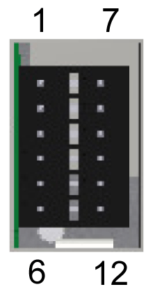
Connection CN8
|
Pin |
Designation |
Meaning |
Range |
|---|---|---|---|
|
1 |
DQ0 |
– |
– |
|
2 |
DQ1 |
– |
– |
|
3 |
DQ2 |
– |
– |
|
4 |
DQ3 |
– |
– |
|
5 |
24V1 |
Supply voltage DQ0 - DQ7 |
-15% / +25% |
|
6 |
0V3 |
Supply voltage DQ0 - DQ7 |
– |
|
7 |
DQ4 |
– |
– |
|
8 |
DQ5 |
– |
– |
|
9 |
DQ6 |
– |
– |
|
10 |
DQ7 |
– |
– |
|
11 |
24V2 |
Supply voltage DQ0 - DQ7 |
-15% / +25% |
|
12 |
0V4 |
Supply voltage DQ0 - DQ7 |
– |
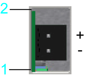
Connection CN9
|
Pin |
Designation |
Meaning |
Range |
|---|---|---|---|
|
1 |
0V |
Supply voltage |
– |
|
2 |
+24V |
Supply voltage |
-15% / +25% |
NOTE: TM5 connection is not active.
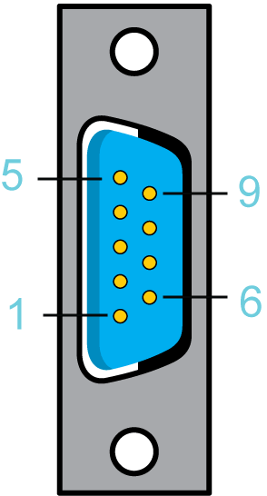
Connection CN11
|
Pin |
Designation |
Meaning |
|---|---|---|
|
1 |
– |
Reserved |
|
2 |
CAN_L |
Bus line (low) |
|
3 |
CAN GND |
– |
|
4 |
– |
Reserved |
|
5 |
– |
Reserved |
|
6 |
CAN GND |
– |
|
7 |
CAN_H |
Bus line (high) |
|
8 |
– |
Reserved |
|
9 |
– |
Reserved |
NOTE: TM5 System can only be connected to the Sercos bus, this means, the connection of the TM5 System to the PacDrive controller can only occur via a Sercos bus interface TM5NS31. A connection of TM5 System via CAN bus and a CANopen interface module is not supported.
CN12 - Master Encoder Input (Hiperface)
The Hiperface connection consists of a standard, differential, digital connection (RS-485 = 2 wires), a differential, analog connection (sine- and cosine signal = 4 wires), and a mains connection to supply the encoder (+10V, GND = 2 wires).
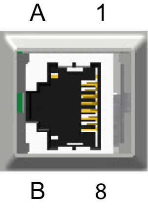
Connection CN12 - Master encoder input (Hiperface)
|
Pin |
Designation |
Meaning |
|---|---|---|
|
1 |
COS |
Cosine track |
|
2 |
REFCOS |
Reference signal cosinus |
|
3 |
SIN |
Sinusoidal trace |
|
4 |
RS485+ |
Parameter channel + |
|
5 |
RS485- |
Parameter channel - |
|
6 |
REFSIN |
Reference signal sine |
|
7 |
– |
Reserved |
|
8 |
– |
Reserved |
|
A |
Encoder supply (+) |
– |
|
B |
GND |
– |
CN12 - Master Encoder Input (Incremental)

Connection CN12 - Master encoder input (incremental)
|
Pin |
Designation |
Meaning |
|---|---|---|
|
1 |
Trace B+ |
– |
|
2 |
Trace B- |
– |
|
3 |
Trace A+ |
– |
|
4 |
Trace N+ |
– |
|
5 |
Trace N- |
– |
|
6 |
Trace A- |
– |
|
7 |
– |
Reserved |
|
8 |
– |
Reserved |
|
A |
Encoder supply (+) |
– |
|
B |
GND |
– |