|
1 |
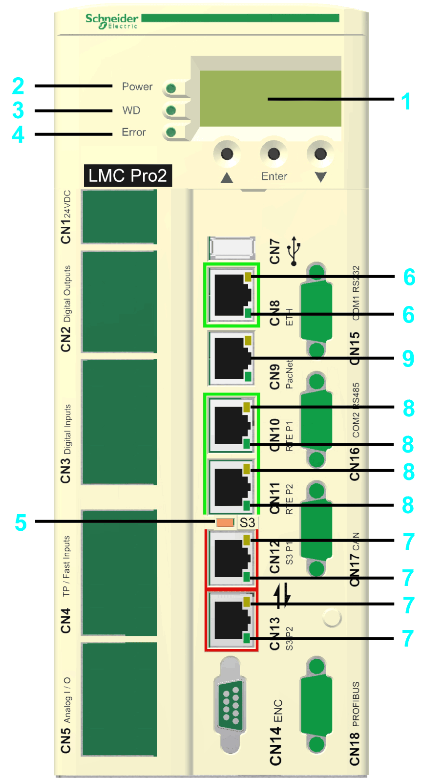
4-line Liquid Crystal Display (LCD) |
|
2 |
|
|
3 |
|
|
4 |
|
|
5 |
|
|
6 |
|
|
7 |
|
|
8 |
|
|
9 |
PacNet LED indicators (not used) |

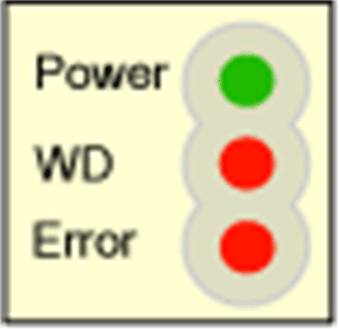
If the cover of the controller is closed, you see 3 vertically arranged LED indicators, which signify various operating states or detected errors:
oPower
oWD (watchdog indicator)
oError (error display)

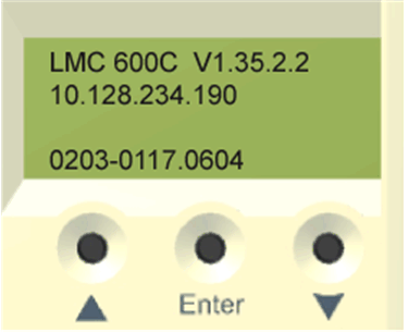
In addition to the LED indicators, further information about the operating status of the controller is given on the 4-line Liquid Crystal Display (LCD).
|
Line 1 |
Controller type and firmware version |
|
Line 2 |
Current IP address of the controller |
|
Line 3 |
– |
|
Line 4 |
PFPGA version/PIC version |
The Power LED indicator indicates the state of the control voltage in the UPS status.
|
LED indicator status |
Meaning |
|---|---|
|
Off |
The control voltage (24 Vdc) is absent or under-voltage. |
|
On |
Normal operation; control voltage in the normal range. |
|
Flashes |
UPS active. |
The WD (watchdog) LED indicator of the watchdog hardware module is used to monitor the controller.
|
LED indicator status |
Meaning |
|---|---|
|
Off |
Normal operation. |
|
On |
An unrecoverable error was detected or the controller is in initialization phase. Press the reset button to reset and reboot the controller. |
An unrecoverable error is a serious hardware or software issue that requires intervention.
When this error is detected, the following actions are performed:
oThe controller is stopped.
oThe optional modules are reset.
oThe digital and analog outputs are reset.
oThe wd (watchdog) relay output is opened.
The Error LED indicator indicates detected errors. The table lists the possible display conditions and their accompanying error descriptions.
|
LED indicator status |
Meaning |
|---|---|
|
Off |
Normal operation. |
|
Flashes slowly (1.7 Hz) |
Error of class 3 and 4 active. Refer to the EcoStruxure Machine ExpertOnline Help\Diagnostics User Guide\System Diagnostic\Diagnostic Classes. |
|
Flashes quickly (10 Hz) |
Controller boot completed, last boot was not successful. See diagnostic message 209 last boot failed. Controller performed a minimal boot. |
|
Flashes fast and slowly alternately |
Firmware download via Sercos is active or controller is in initialization phase |
|
On |
An error was detected during the boot. |
The Error LED indicator is flashing on after BIOS is started. Once the operating system, user configuration, user parameters, and the IEC program have been loaded and the IEC program has been started successfully, the Error LED indicator is switched off again. The boot procedure is now complete.
The S3 LED indicator indicates the state and the phases of the Sercos communication.
|
LED indicator color / status |
Meaning |
Instructions/information for the user |
Notes |
|---|---|---|---|
|
Off |
No Sercos communication |
– |
– |
|
Orange |
The device is in a communication phase CP0 up to and including CP3. |
– |
SERC3.State = 0..3 |
|
Green |
Sercos communication in communication phase CP4 without error detected. |
– |
SERC3.State = 4 |
|
Red |
Detected communication error. |
Reset condition: DiagQuit |
SERC3.State = 11 |
Ethernet Status LED Indicators
The Ethernet connector of PacDrive LMC Pro has two LED indicators. One LED indicator is green, the other is yellow.
|
LED indicator |
State |
Meaning |
|---|---|---|
|
Green |
On |
Connection established |
|
Green |
Flashing |
Data traffic |
|
Green |
Off |
No connection, for example, no cable connected, or connected device has no power |
|
Yellow |
On |
100 MBit/s connection |
|
Yellow |
Off |
10 MBit/s connection |
The Ethernet connector of PacDrive LMC Pro2 has two LED indicators. One LED indicator is green (above), the other is yellow/green (below).
|
LED indicator |
State |
Meaning |
|---|---|---|
|
Green (above) |
On |
Connection established |
|
Green (above) |
Off |
No connection, for example, no cable connected, or connected device has no power |
|
Green (below) |
Flashing |
1000 MBit/s (1 GBit/s) connection with data traffic |
|
Yellow (below) |
Flashing |
10/100 MBit/s connection with data traffic |
|
Yellow/Green (below) |
Off |
No data traffic |
Each Sercos connector has two LED indicators. One LED indicator is green, the other is yellow.
|
LED indicator |
State |
Meaning |
|---|---|---|
|
Yellow |
On |
Connection established |
|
Off |
No cable connected or connected device has no power. |
|
|
Green |
On |
Active network traffic |
|
Off |
No active network traffic |
Protocol-specific Status LED Indicators
LED indicators EtherCAT master
|
LED indicator |
Color |
State |
Meaning |
|---|---|---|---|
|
LINK/RJ45 Ch0 & Ch1 |
green LED indicator |
||
|
Green |
On |
A connection to Ethernet exists. |
|
|
Off |
Off |
The device has no connection to Ethernet. |
|
|
RJ45 Ch0 & Ch1 |
yellow LED indicator |
||
|
Yellow |
Flashing cyclic with 2.5 Hz |
The device sends/receives Ethernet frames. |
|
LED indicators EtherCAT slave
|
LED indicator |
Color |
State |
Meaning |
|---|---|---|---|
|
LINK/RJ45 Ch0 & Ch1 |
green LED indicator |
||
|
Green |
On |
A connection to Ethernet exists. |
|
|
Green |
Flashing cyclic with 2.5 Hz |
The device sends/receives Ethernet frames. |
|
|
Off |
Off |
The device has no connection to Ethernet. |
|
|
RJ45 Ch0 & Ch1 |
yellow LED indicator |
||
|
– |
– |
The LED indicator is not being used. |
|
LED indicators EtherNet/IP scanner (master)
|
LED indicator |
Color |
State |
Meaning |
|---|---|---|---|
|
LINK/RJ45 Ch0 & Ch1 |
green LED indicator |
||
|
Green |
On |
A connection to Ethernet exists. |
|
|
Off |
Off |
The device has no connection to Ethernet. |
|
|
ACT/RJ45 Ch0 & Ch1 |
yellow LED indicator |
||
|
Yellow |
Flashes |
The device sends/receives Ethernet frames. |
|
LED indicators EtherNet/IP adapter (slave)
|
LED indicator |
Color |
State |
Meaning |
|---|---|---|---|
|
LINK/RJ45 Ch0 & Ch1 |
green LED indicator |
||
|
Green |
On |
A connection to Ethernet exists. |
|
|
Off |
Off |
The device has no connection to Ethernet. |
|
|
ACT/RJ45 Ch0 & Ch1 |
yellow LED indicator |
||
|
Yellow |
Flashes |
The device sends/receives Ethernet frames. |
|
LED indicators PROFINET controller
|
LED indicator |
Color |
State |
Meaning |
|---|---|---|---|
|
LINK/RJ45 Ch0 & Ch1 |
green LED indicator |
||
|
Green |
On |
A connection to Ethernet exists. |
|
|
Off |
Off |
The device has no connection to Ethernet. |
|
|
RX/TX/RJ45 Ch0 & Ch1 |
yellow LED indicator |
||
|
Yellow |
Flashes |
The device sends/receives Ethernet frames. |
|
LED indicators PROFINET device
|
LED indicator |
Color |
State |
Meaning |
|---|---|---|---|
|
LINK/RJ45 Ch0 & Ch1 |
green LED indicator |
||
|
Green |
On |
A connection to Ethernet exists. |
|
|
Off |
Off |
The device has no connection to Ethernet. |
|
|
RX/TX/RJ45 Ch0 & Ch1 |
yellow LED indicator |
||
|
Yellow |
Flashes |
The device sends/receives Ethernet frames. |
|