Wiring with Lexium 62 DC Link Terminal
Wiring with Lexium 62 DC Link Terminal allows the connection of the bus bar modules of two or more rows of:
oLexium 62 devices that are not directly adjacent within the same control cabinet, or
oLexium 62 devices that are located in separate control cabinets.
When wiring with Lexium 62 DC Link Terminal, rows without power supply unit are supplied by rows with power supply units.
A row or device island is a combination of the following Lexium 62 devices which are directly connected via the bus bar module:
oLexium 62 Power Supply
oLexium 62 Cabinet Drive
oLexium 62 DC Link Support Module
oLexium 62 Connection Module
NOTE: Wiring with Lexium 62 DC Link Terminal is subject to electrical restrictions. Refer to the admissible topologies and to the electrical restrictions.
Topologies Allowed for Wiring with Lexium 62 DC Link Terminal
The seven topologies presented hereafter include Lexium 62 DC Link Support Modules. However, a Lexium 62 DC Link Support Module is only mandatory for longer cable lengths or if a Single Drive LXM62DC13 is present in a row without Lexium 62 Power Supply.
NOTE: Each device island without its own Lexium 62 Power Supply requires the 24 V supply from the Lexium 62 DC Link Terminal.
NOTE:
oWiring with Lexium 62 DC Link Terminal does not support ring topologies.
oWiring with Lexium 62 DC Link Terminal supports a maximum of six rows or device islands.
oThe 24 V and 0 V can be distributed via the Lexium 62 DC Link Terminal over two or more device islands.
oInstead of distributing the 24 V over several rows, an external 24 V supply can also be connected directly to the Lexium 62 DC Link Terminal for rows without Lexium 62 Power Supply modules.
|
|
|
FIRE, ELECTRIC SHOCK OR ARC FLASH |
|
Use the Lexium 62 DC Link Terminal to link Lexium 62 devices only. |
|
Failure to follow these instructions will result in death or serious injury. |
Topology 1: Coupling of Two (or More) Rows in Control Cabinet with a Separate 24 V Supply
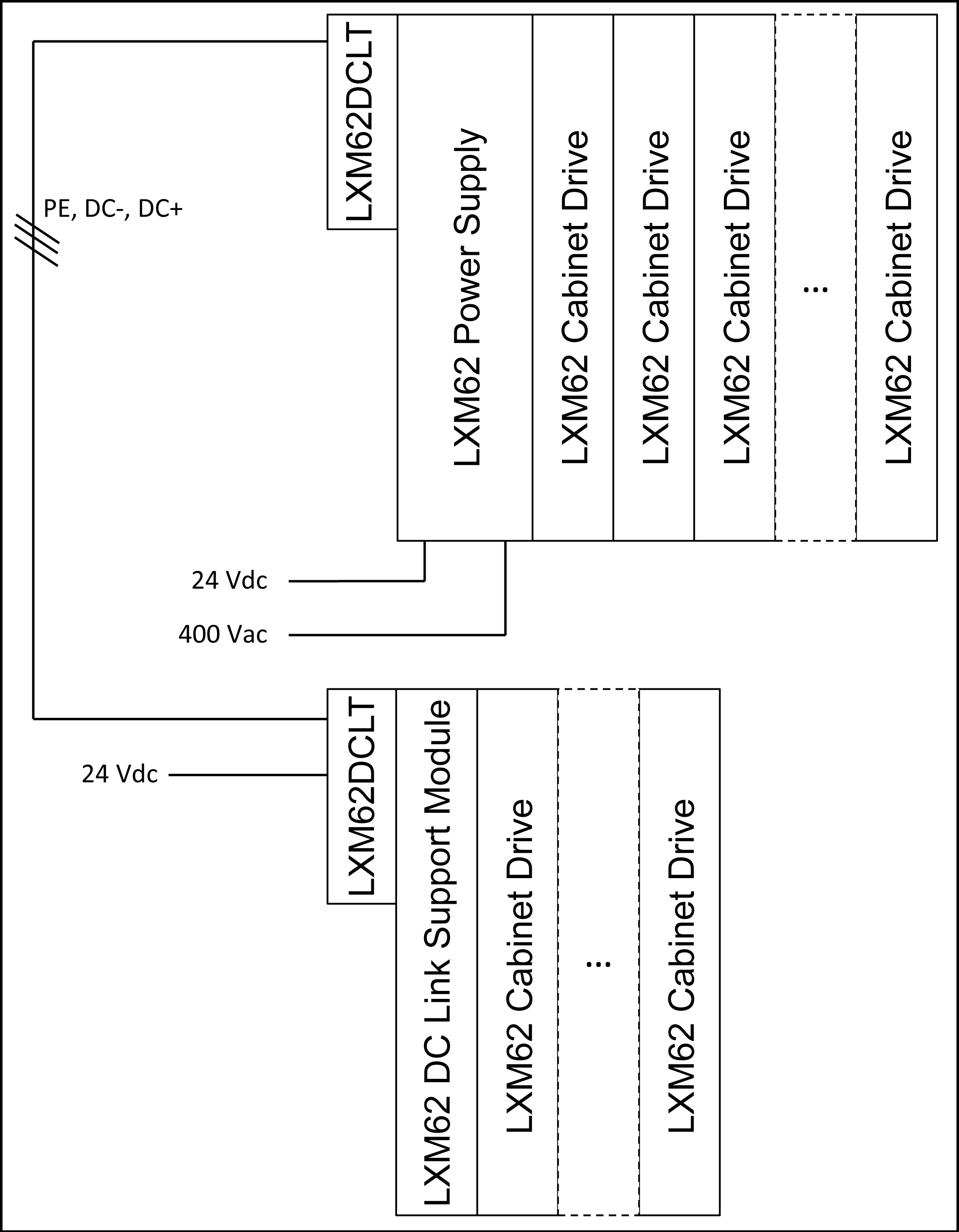
LXM62DCLT: Lexium 62 DC Link Terminal
The 24 V and 0 V terminals always have to be mounted to the Bus Bar Module, even if no wire is connected to the terminals.
|
|
|
ELECTRIC SHOCK |
|
oAlways install the full complement of the five connectors and the retaining bracket of the Lexium 62 DC Link Terminal. oAlways wire at least the PE, DC- and DC+ terminals out of the 5 installed connectors. |
|
Failure to follow these instructions will result in death or serious injury. |
Topology 2: Coupling of Two (or More) Rows in a Control Cabinet Without a Separate 24 V Supply
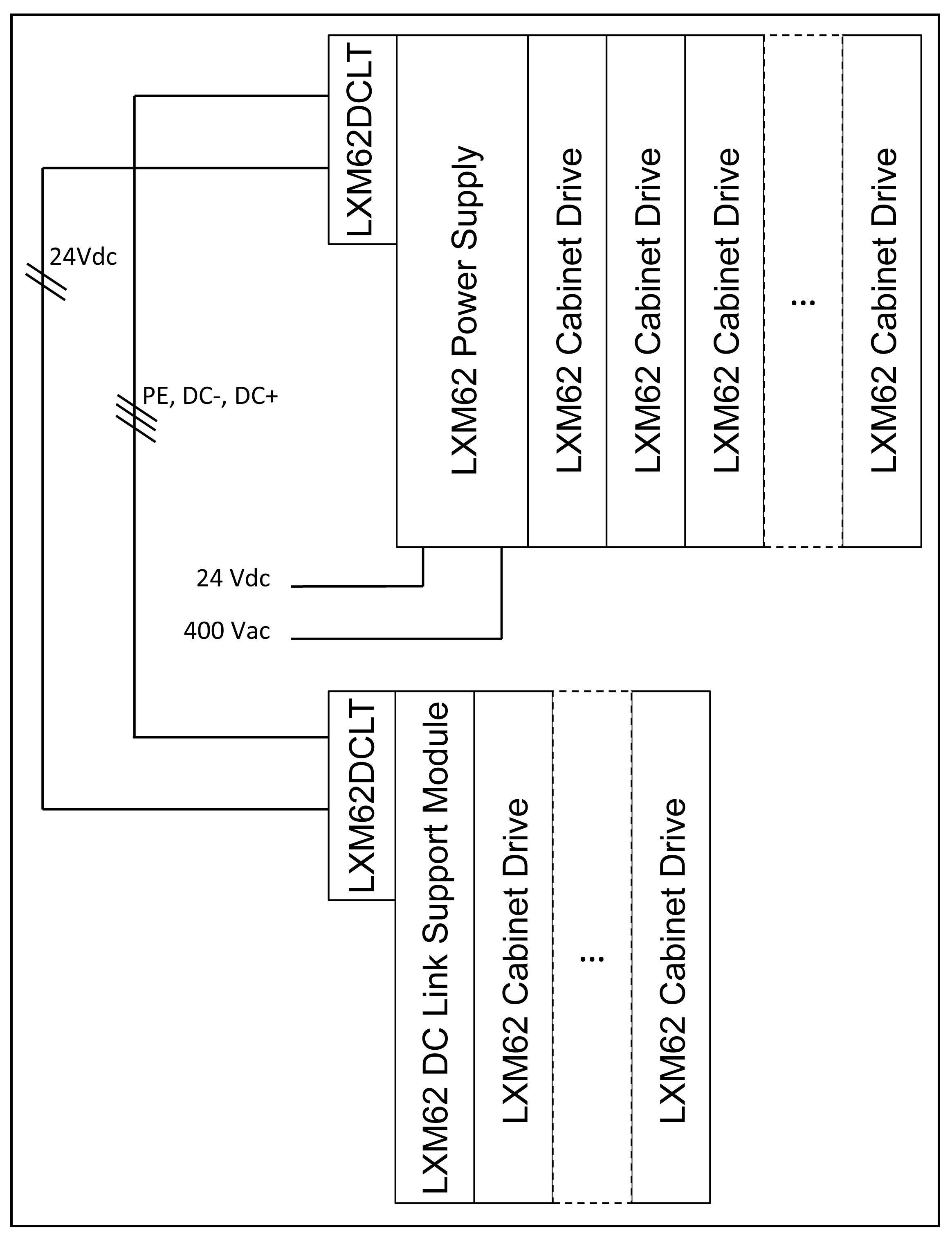
LXM62DCLT: Lexium 62 DC Link Terminal
Topology 3: Coupling of Two Power Supplies
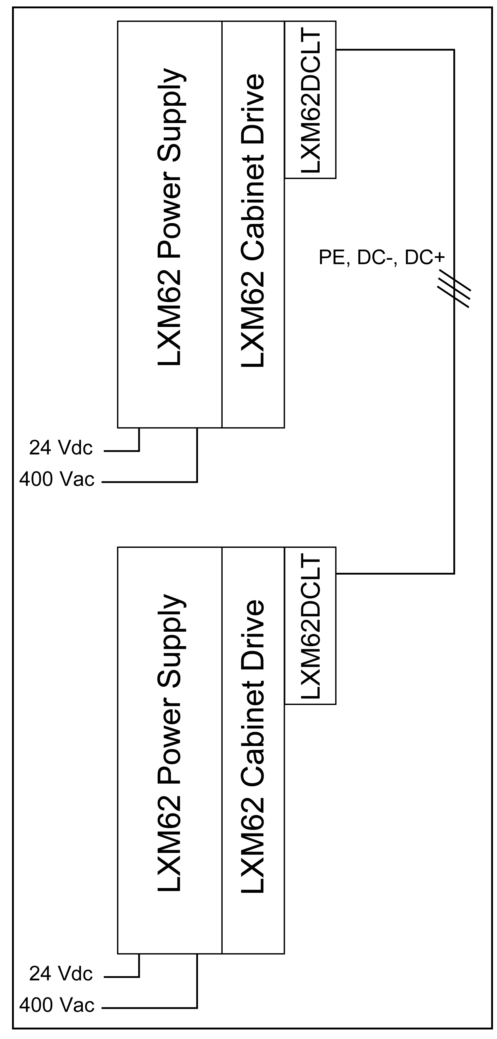
LXM62DCLT: Lexium 62 DC Link Terminal
NOTE:
oThe Lexium 62 Power Supply modules are connected in parallel.
oThe Lexium 62 Power Supply modules must be located in the same control cabinet.
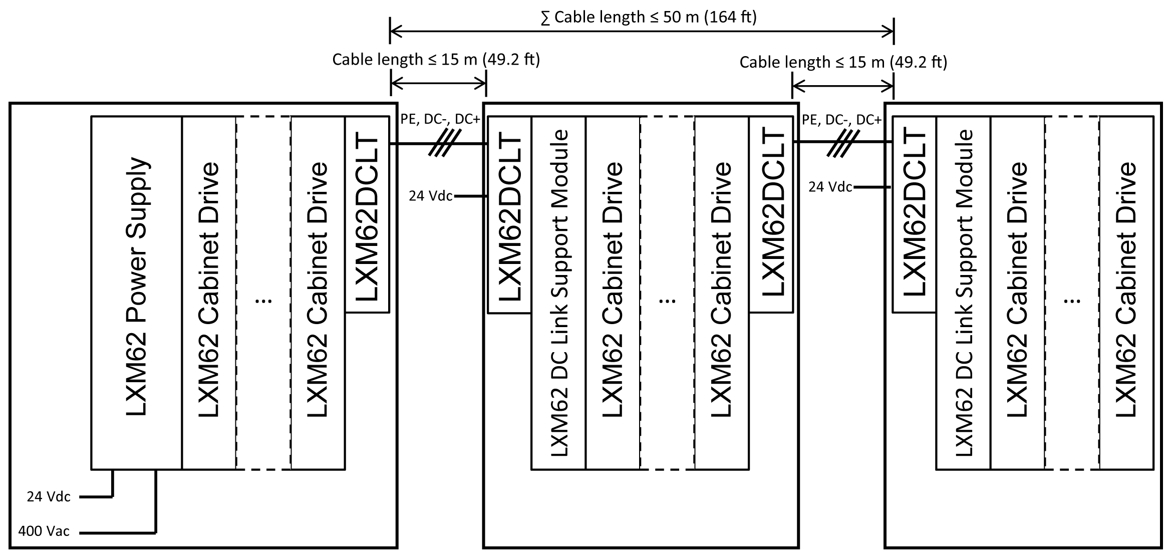
Topology 4: Coupling of Two Control Cabinets
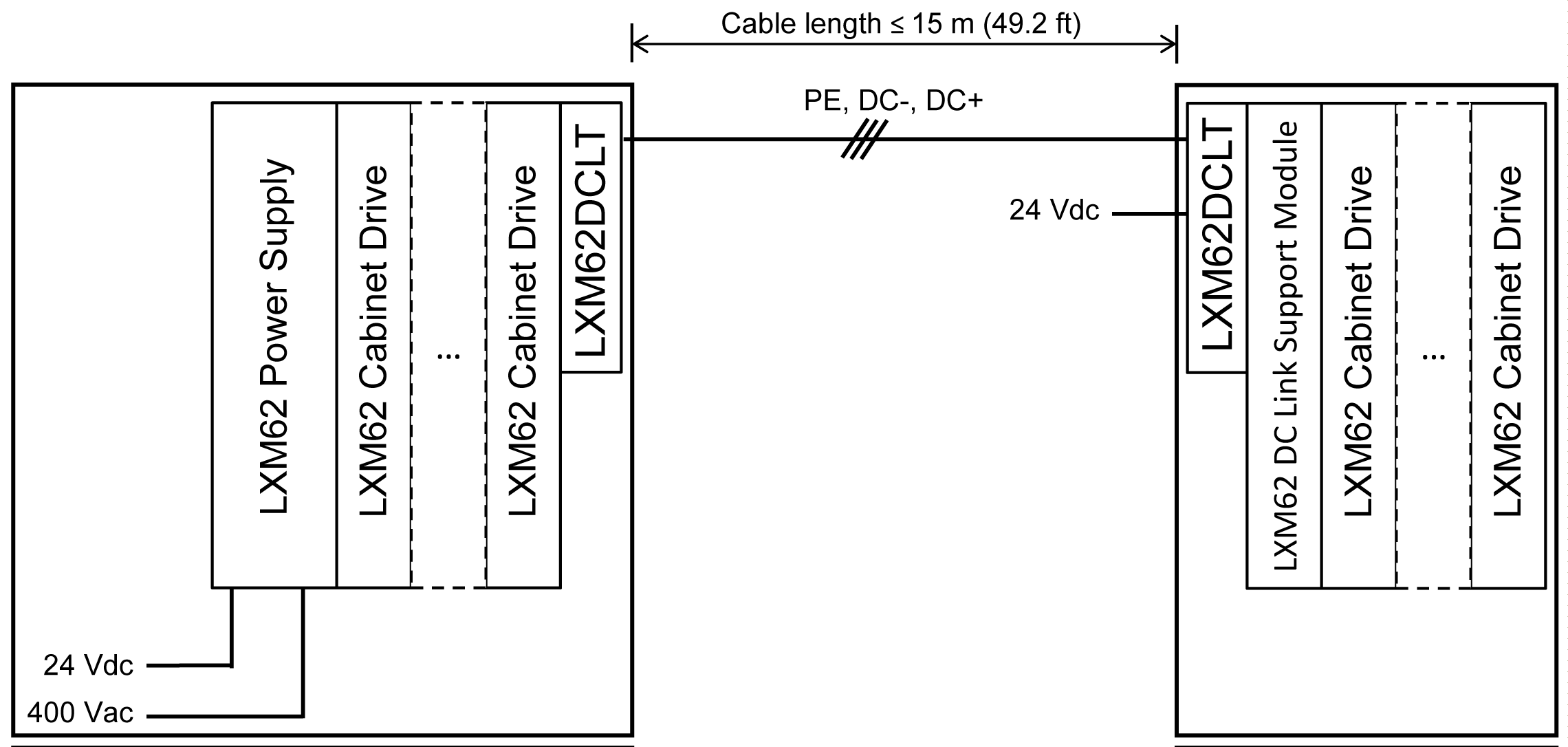
LXM62DCLT: Lexium 62 DC Link Terminal
Topology 5: Coupling of More Than Two Control Cabinets in Line Topology
LXM62DCLT: Lexium 62 DC Link Terminal
NOTE:
oThe Lexium 62 Power Supply modules must be located in the same control cabinet.
oUp to 6 Lexium 62 device islands are allowed in this topology.
Topology 6: Coupling of More Than Two Control Cabinets in Star Topology
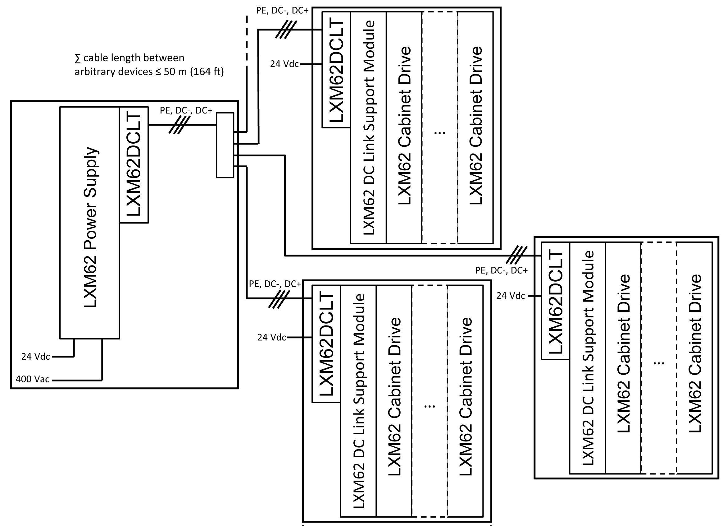
LXM62DCLT: Lexium 62 DC Link Terminal
NOTE:
oThe Lexium 62 Power Supply modules must be located in the same control cabinet.
oUp to 6 Lexium 62 device islands are allowed in this topology.
oExternal terminals (for example, for cap rail) are necessary to realize star connections.
oThe maximum cable length of one single connection between any Lexium 62 device island and the nearest Lexium 62 device island is 15 m (49.2 ft).
Topology 7: Coupling of More Than Two Control Cabinets in Mixed Line and Star Topology
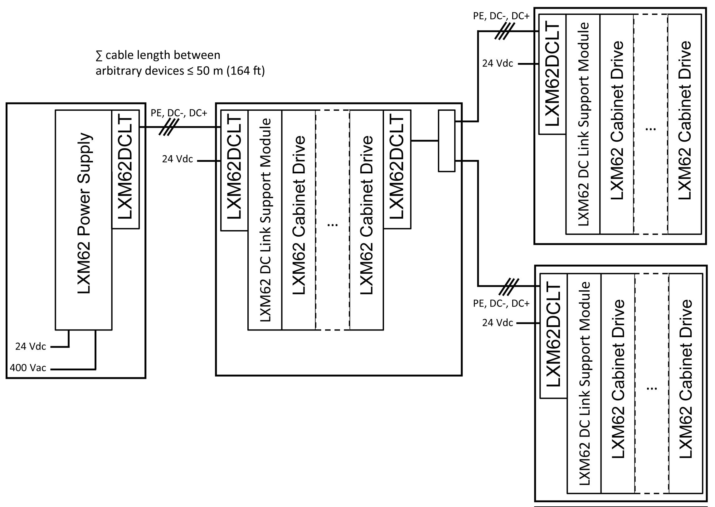
LXM62DCLT: Lexium 62 DC Link Terminal
NOTE:
oThe Lexium 62 Power Supply modules must be located in the same control cabinet.
oUp to 6 Lexium 62 device islands are allowed in this topology.
oExternal terminals (for example, for cap rail) are necessary to realize star connections.
Electrical Restrictions for Wiring with Lexium 62 Terminal Link
|
Criteria |
Description |
|---|---|
|
Absolute cable length limits |
oThe maximum cable length of one single connection between any Lexium 62 device island and the nearest Lexium 62 device island is 15 m (49.2 ft). oThe maximum overall cable length between one Lexium 62 device and any other Lexium 62 device connected using the wiring via Lexium 62 DC Link Terminal is 50 meters (164 ft). |
|
Lexium 62 DC Link Support Module |
One Lexium 62 DC Link Support Module must be installed per row without Lexium 62 Power Supply if: othe overall cable length between the row and the next row with a Lexium 62 Power Supply or Lexium 62 DC Link Support Module is longer than 3 m (9.84 ft.) oa Lexium 62 drive of type LXM62DC13 is present in the row. NOTE: More than one Lexium 62 DC Link Support Module may be necessary in this case. NOTE: The overall cable length means the sum of single wiring connections with Lexium 62 DC Link Terminal. |
|
Power supply |
oThe Lexium 62 Power Supply modules which are connected via Lexium 62 DC Link Terminal must be located within one control cabinet. oThe mains supply of the Lexium 62 Power Supply modules which are connected via Lexium 62 DC Link Terminal must be operated using the same mains contactor. |
|
Single Drive LXM62DC13 |
oThe drives of type Single Drive LXM62DC13 have to be used in combination with a Lexium 62 Power Supply or a Lexium 62 DC Link Support Module in the same row. oIn a row without Lexium 62 Power Supply, one Lexium 62 DC Link Support Module has to be installed per Single Drive LXM62DC13. |
|
Cable/wire cross section |
oThe ampacity of the Lexium 62 DC Link Terminal depends on the usage of suitable cables/wires and on the installation method of the cables/wires. oWhen using smaller cable/wire cross-sections, and if the system is able to drive permanently a larger current than permitted for cable/wire cross-sections, external fuses for current limiting must be integrated into the connection via Lexium 62 DC Link Terminal. |
|
|
|
FIRE HAZARD |
|
oDo not exceed an overall cable length of 3 m (9.84 ft) between any row without Lexium 62 DC Link Support Module or Lexium 62 Power Supply module and the next row with a Lexium 62 Power Supply module or Lexium 62 DC Link Support Module. oInstall a Lexium 62 DC Link Support Module for each drive of type LXM62DC13 in rows without Lexium 62 Power Supply module. oInstall all Lexium 62 Power Supply modules with linked DC Bus in the same control cabinet sharing the same mains contactor. |
|
Failure to follow these instructions will result in death or serious injury. |
|
|
|
FIRE, ELECTRIC SHOCK OR ARC FLASH |
|
oDo not install more than three Lexium 62 Power Supply modules on the same DC Bus. oThe maximum continuous current at any point of the DC link and 24V/0V connection must not exceed 120 A. |
|
Failure to follow these instructions will result in death or serious injury. |
|
|
|
IMPROPER WIRING BETWEEN CONTROL CABINETS CAUSES ELECTRIC SHOCK |
|
oOnly use appropriate and certified cables according to the applicable standards. oOnly use the cables with the appropriate cross-sections. oOnly use cables outside the control cabinet. oObserve the bending radius of the cable/wire specification of the manufacturer. oThoroughly verify the cables/wires for defects and/or damages after the installation. oUse cable ducts and other appropriate measures outside of the control cabinet protecting the cables/wires from damage and mechanical stress. oRemove insulation accurately according to the stripping length of the cable conductor. |
|
Failure to follow these instructions will result in death or serious injury. |
|
|
|
HIGH ELECTROMAGNETIC RADIATION |
|
oDo not exceed a cable length of 15 m (49.2 ft) for single connections using Lexium 62 DC Link Terminal. oDo not exceed an overall cable length of 50 meters (164 ft) between one Lexium 62 device and any other Lexium 62 device connected via a Lexium 62 DC Link Terminal. |
|
Failure to follow these instructions can result in death, serious injury, or equipment damage. |


