Connection Details - Lexium 62 Cabinet Drive
The DC bus voltage and the 24 Vdc control voltage are distributed and the protective conductor is connected via the Bus Bar Module.

Electrical connection - Bus Bar Module
|
Pin |
Designation |
Description |
|---|---|---|
|
1 |
|
Protective ground (earth) |
|
2 |
DC- |
DC bus voltage - |
|
3 |
DC+ |
DC bus voltage + |
|
4 |
24 V |
Supply voltage + |
|
5 |
0 V |
Supply voltage - |
The Sercos connection is used for the communication between the controller and the drive.
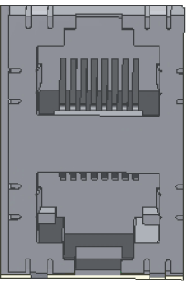
Electrical connection - Sercos
|
Pin |
Designation |
Description |
|---|---|---|
|
1.1 |
Eth0_Tx+ |
Positive transmission signal |
|
1.2 |
Eth0_Tx- |
Negative transmission signal |
|
1.3 |
Eth0_Rx+ |
Positive receiver signal |
|
1.4 |
N.C. |
Reserved |
|
1.5 |
N.C. |
Reserved |
|
1.6 |
Eth0_Rx- |
Negative receiver signal |
|
1.7 |
N.C. |
Reserved |
|
1.8 |
N.C. |
Reserved |
|
2.1 |
Eth1_Tx+ |
Positive transmission signal |
|
2.2 |
Eth1_Tx- |
Negative transmission signal |
|
2.3 |
Eth1_Rx+ |
Positive receiver signal |
|
2.4 |
N.C. |
Reserved |
|
2.5 |
N.C. |
Reserved |
|
2.6 |
Eth1_Rx- |
Negative receiver signal |
|
2.7 |
N.C. |
Reserved |
|
2.8 |
N.C. |
Reserved |
CN4 - Digital Inputs / Outputs
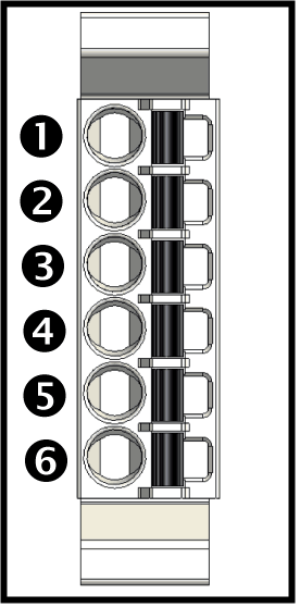
The connection CN4 provides several digital inputs and outputs on the drive:
oThe digital inputs A_DI1 / A_DI2 (Single Drive) or A_DI1, A_DI2 / B_DI1, B_DI2 (Double Drive) can be configured as digital inputs or as Touchprobe inputs via the EcoStruxure Machine Expert Logic Builder.
oThe digital inputs A_DI5 /A_DI6 (Single Drive) or A_DI5, A_DI6 / B_DI5, B_DI6 can be configured as digital inputs or as digital outputs via the EcoStruxure Machine Expert Logic Builder.
oThe filter time constant of the digital inputs can be set to 1 ms or 5 ms.
oThe filter time constant of the Touchprobe inputs is fixed at 100 µs.
Single Drive
Double Drive
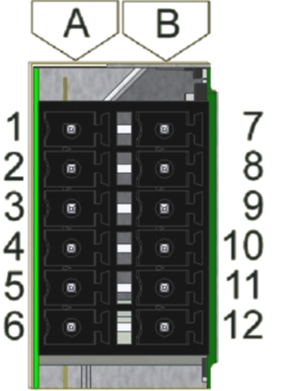
Electrical connection - digital inputs / outputs
|
Pin |
Designation |
Description |
|---|---|---|
|
1 |
A_DI0 |
Axis A – Digital input 0 - Touchprobe |
|
2 |
A_DI1 |
Axis A – Digital input 1 - Touchprobe |
|
3 |
A_DI2 |
Axis A – Digital input 2 |
|
4 |
A_DI3 |
Axis A – Digital input 3 |
|
5 |
A_DI4 |
Axis A – Digital input / output 4 |
|
6 |
A_DI5 |
Axis A – Digital input / output 5 |
|
7 |
B_DI0 |
Axis B – Digital input 0 - Touchprobe (only Double Drive) |
|
8 |
B_DI1 |
Axis B – Digital input 1 - Touchprobe (only Double Drive) |
|
9 |
B_DI2 |
Axis B – Digital input 2 (only Double Drive) |
|
10 |
B_DI3 |
Axis B – Digital input 3 (only Double Drive) |
|
11 |
B_DI4 |
Axis B – Digital input/output 4 (only Double Drive) |
|
12 |
B_DI5 |
Axis B – Digital input/output 5 (only Double Drive) |
The 24 V DIO supply connector supplies the digital inputs/outputs of the drives with the required energy. The connection 0V1 is internally connected to 0V2 and the connection 24V1 is internally connected to 24V2 electrically.
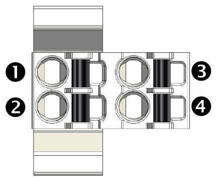
Electrical connection - 24 V input
|
Pin |
Designation |
Description |
|---|---|---|
|
1 |
24V1 |
Digital I/O supply voltage Axis A |
|
2 |
0V1 |
|
|
3 |
24V2 |
Digital I/O supply voltage Axis B |
|
4 |
0V2 |
NOTE:
For the digital inputs/outputs, if the 24 V supply is interconnected to any additional devices via the connection CN5, the maximum current carrying capacity must be respected:
oContinuous current carrying capacity of the plug-in connectors: 3 A
oMaximum current carrying capacity of the plug-in connectors: 4 A, 1 s
The number of the devices that can be connected depends on the application.
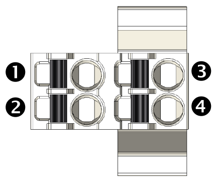
The Inverter Enable signal supplies the gate driver with voltage. In this way, the STO (Safe Torque Off) requirements according to EN 61508 and ISO 13849-1 are met. IEA1 is internally connected with IEA2 electrically, and IEB1 is internally connected with IEB2 electrically.
|
CN6 - Inverter Enable |
(CN6/CN11 - Inverter Enable) |
|---|---|
|
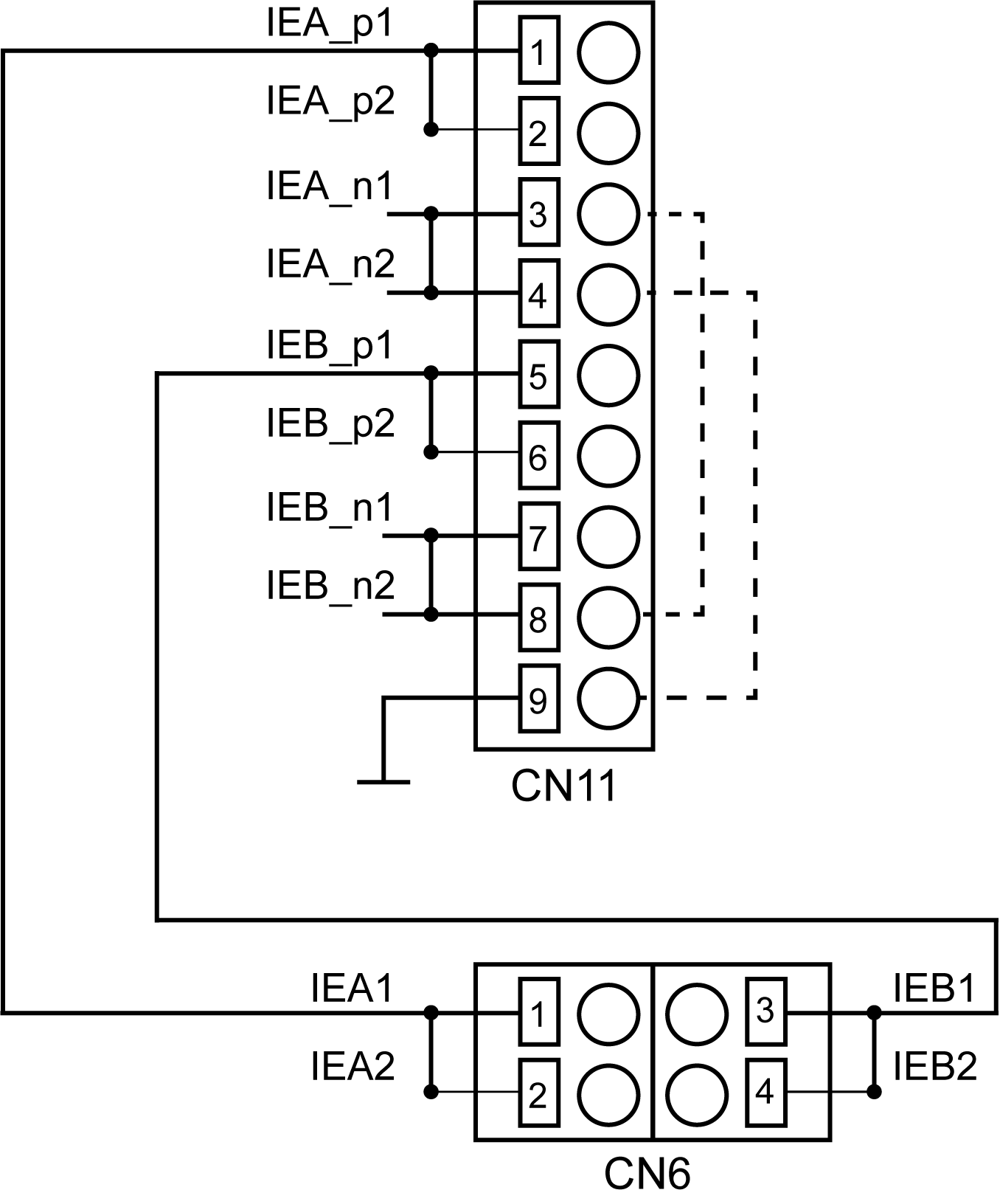
— Internal connections between CN6 and CN11 - - - Possible connection to use the two-channel Inverter Enable as a single-channel Inverter Enable |
Electrical connection - Inverter Enable
|
Pin |
Designation |
Description |
|---|---|---|
|
1 |
IEA1 |
Inverter Enable signal for axis A (with CN11 PIN 1, CN11 PIN 2 and CN6 PIN 2 jumpered) |
|
2 |
IEA2 |
Inverter Enable signal for axis A (with CN11 PIN 2, CN11 PIN 1 and CN6 PIN 2 jumpered) |
|
3 |
IEB1 |
Inverter Enable signal for axis B (with CN11 PIN 5, CN11 PIN 6 and CN6 PIN 4 jumpered) |
|
4 |
IEB2 |
Inverter Enable signal for axis B (with CN11 PIN 6, CN11 PIN 5 and CN6 PIN 3 jumpered) |
NOTE:
For the gate drivers connected via the connection CN6, the maximum current carrying capacity must be respected:
oContinuous current carrying capacity of the plug-in connectors: 3 A
oMaximum current carrying capacity of the plug-in connectors: 4 A, 1 s
oMaximum consumption per drive: 30 mA
The number of the devices that can be connected depends on the application.
The Hiperface connection consists of a standard, differential, digital connection (RS-485 = 2 wires), a differential, analog connection (sine- and cosine signal = 4 wires), and a mains connection to supply the encoder (+10 V, GND = 2 wires).
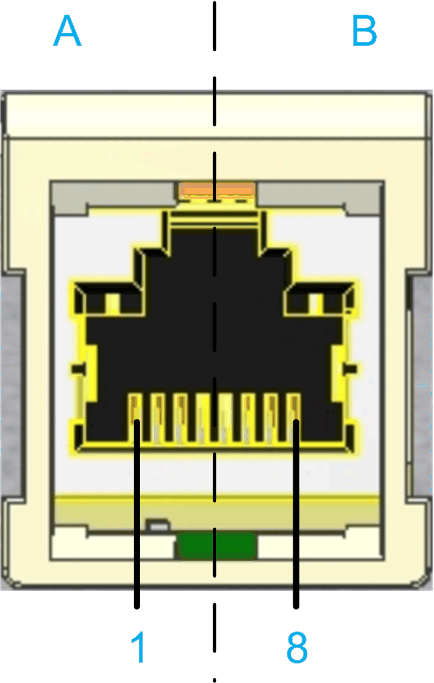
CN7 / CN9 - encoder connector
|
Pin |
Designation |
Description |
|---|---|---|
|
1 |
Cos |
Cosine track axis A/B |
|
2 |
RefCos |
Reference signal cosine axis A/B |
|
3 |
Sin |
Sine track axis A/B |
|
4 |
RS485+ |
Positive RS-485 signal axis A/B |
|
5 |
RS485- |
Negative RS-485 signal axis A/B |
|
6 |
RefSin |
Reference signal Sine axis A/B |
|
7 |
N.C. |
Reserved |
|
8 |
N.C. |
Reserved |
|
A |
P10V |
Supply voltage encoder A/B |
|
B |
GND |
0 V A/B return |
NOTE: With the 5 V encoder adapter, it is also possible to connect encoders with 5 V supply voltage to the Lexium 62 Cabinet Drive.
The motor signals U, V, and W supply the motor with the required energy. The temperature signals are connected to a temperature sensor to measure the temperature of the motor. The holding brake output supplies the holding brake in the motor with the required energy.
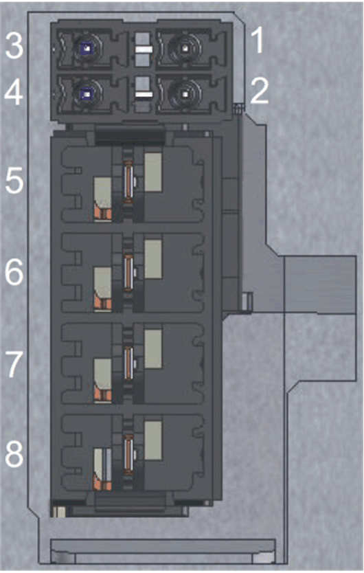
CN8/ CN10 - motor connector
|
Pin |
Designation |
Description |
|---|---|---|
|
1 |
ϑ− |
Temperature negative signal |
|
2 |
ϑ+ |
Temperature positive signal |
|
3 |
BR- |
Brake negative signal |
|
4 |
BR+ |
Brake positive signal |
|
5 |
PE |
Protective Earth (ground) |
|
6 |
U |
Motor phase U |
|
7 |
V |
Motor phase V |
|
8 |
W |
Motor phase W |
Electrical connection - motor connector
|
Motor cable(1) |
Motor connectors |
Description |
|
|---|---|---|---|
|
Label of cable core |
Color of cable core |
Label |
|
|
1 |
Black |
U |
Motor phase U - Axis A/B |
|
2 |
Black |
V |
Motor phase V - Axis A/B |
|
3 |
Black |
W |
Motor phase W - Axis A/B |
|
– |
Green/Yellow |

|
Protective ground (earth) - Axis A/B |
|
5 |
Black |
1 ϑ− |
Temperature negative signal - Axis A/B |
|
6 |
Black |
ϑ+ |
Temperature positive signal - Axis A/B |
|
7 |
Black |
BR- |
Holding brake negative signal - Axis A/B |
|
8 |
Black |
BR+ |
Holding brake positive signal - Axis A/B |
|
(1) Order numbers: VW3E1143Rxxx, VW3E1144Rxxx, VW3E1145Rxxx |
|||
The insulation-stripped length of the wires of the motor connector is 15 mm (0.59 in.). The maximum length of the motor supply cable is 75 m (246.06 ft).
CN11 - Inverter Enable 2-Channel
|
CN11 - Inverter Enable 2-Channel |
(CN6/CN11 - Inverter Enable) |
|---|---|

|

— Internal connections between CN6 and CN11 - - - Possible connection to use the two-channel Inverter Enable as a single-channel Inverter Enable |
CN11 - Inverter enable 2-channel
|
Pin |
Designation |
Description |
|---|---|---|
|
1 |
IEA_p1 |
Inverter Enable signal for drive A 24 V (with CN6 PIN 1, CN6 PIN 2 and CN11 PIN 2 jumpered) |
|
2 |
IEA_p2 |
Inverter Enable signal for drive A 24 V (with CN6 PIN 1, CN6 PIN 2 and CN11 PIN 1 jumpered) |
|
3 |
IEA_n1 |
Inverter Enable signal for drive A 0 V external |
|
4 |
IEA_n2 |
Inverter Enable signal for drive A 0 V external |
|
5 |
IEB_p1 |
Inverter Enable signal for drive B 24 V (with CN6 PIN 3, C6 PIN 4 and CN11 PIN 6 jumpered) |
|
6 |
IEB_p2 |
Inverter Enable signal for drive B 24 V (with CN6 PIN 4, C6 PIN 3 and CN11 PIN 5 jumpered) |
|
7 |
IEB_n1 |
Inverter Enable signal for drive B 0 V external |
|
8 |
IEB_n2 |
Inverter Enable signal for drive B 0 V external |
|
9 |
0V_int |
Inverter Enable signal 0 V internal |
CN12 - Encoder Output Simulation
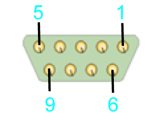
CN12 - Encoder output simulation
|
Pin |
Designation |
Description |
|---|---|---|
|
1 |
B- |
Encoder Output track B / Differential - |
|
2 |
B+ |
Encoder Output track B / Differential + |
|
3 |
A+ |
Encoder Output track A / Differential + |
|
4 |
A- |
Encoder Output track A / Differential - |
|
5 |
n.c. |
- |
|
6 |
n.c. |
- |
|
7 |
Z+ |
Encoder Output track B / Differential + |
|
8 |
Z- |
Encoder Output track B / Differential - |
|
9 |
GND_EXT |
External Ground |