The controller structure corresponds to the classical cascaded closed loop with current controller, velocity controller and position controller. In addition, the reference value of the velocity controller can be smoothed via a filter.
The controllers are tuned one after the other from the "inside" to the "outside" in the following sequence: current control, velocity control, position control.
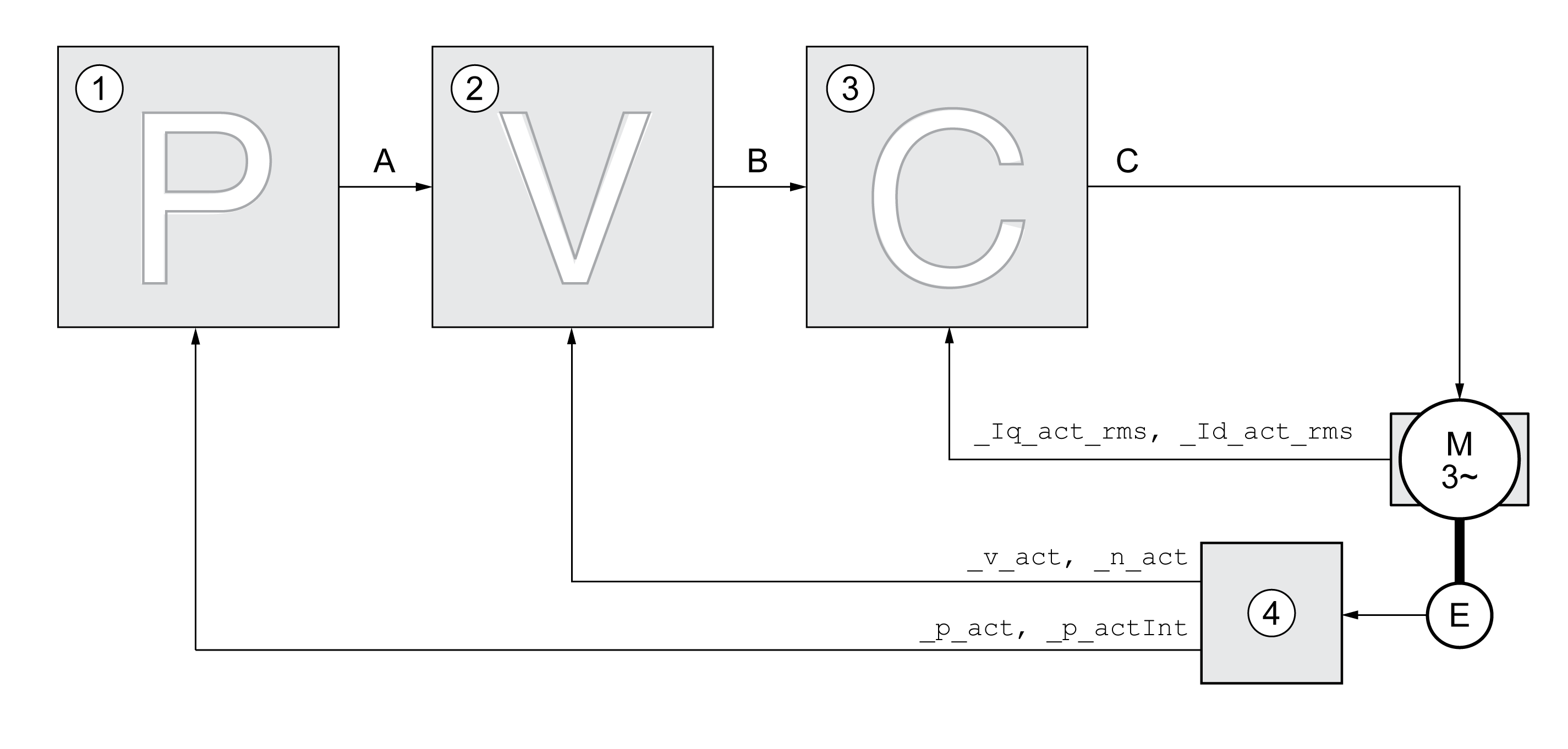
1 Position controller
2 Velocity controller
3 Current controller
4 Encoder evaluation
See chapter Overview of the Controller Structure for a detailed description of the controller structure.
The current controller determines the torque of the motor. The current controller is automatically optimally tuned with the stored motor data.
The velocity controller controls the motor velocity by varying the motor current depending on the load situation. The velocity controller has a decisive influence on the dynamic response of the drive. The dynamics of the velocity controller depend on:
oMoment of inertia of the drive and the controlled system
oPower of the motor
oStiffness and elasticity of the elements in the flow of forces
oBacklash of the drive elements
oFriction
The position controller reduces the difference between the reference position and the actual position of the motor (position deviation) to a minimum. When the motor is at a standstill, the position deviation is close to zero in the case of a well-tuned position controller.
An optimized velocity control loop is a prerequisite for good amplification of the position controller.
This device allows you to use two control loop parameter sets. It is possible to switch form one set of control loop parameter sets to the other during operation. The active control loop parameter set is selected with the parameter CTRL_SelParSet.
The corresponding parameters are CTRL1_xx for the first control loop parameter set and CTRL2_xx for the second control loop parameter set. The following descriptions use the notation CTRL1_xx (CTRL2_xx) if there are no functional differences between the two control loop parameter sets.
|
Parameter name HMI menu HMI name |
Description |
Unit Minimum value Factory setting Maximum value |
Data type R/W Persistent Expert |
Parameter address via fieldbus |
|---|---|---|---|---|
|
Selection of control loop parameter set (non-persistent). Coding see parameter: CTRL_PwrUpParSet Type: Unsigned decimal - 2 bytes Write access via Sercos: CP2, CP3, CP4 Modified settings become effective immediately. |
- 0 1 2 |
UINT16 R/W - - |
Modbus 4402 IDN P-0-3017.0.25 |
|
|
Active control loop parameter set. Value 1: Control loop parameter set 1 is active Value 2: Control loop parameter set 2 is active
A control loop parameter set is active after the time for the parameter switching (CTRL_ParChgTime) has elapsed. Type: Unsigned decimal - 2 bytes |
- - - - |
UINT16 R/- - - |
Modbus 4398 IDN P-0-3017.0.23 |
|
|
Period of time for control loop parameter set switching. In the case of control loop parameter set switching, the values of the following parameters are changed gradually: - CTRL_KPn - CTRL_TNn - CTRL_KPp - CTRL_TAUnref - CTRL_TAUiref - CTRL_KFPp
Such a switching can be caused by - change of the active control loop parameter set - change of the global gain - change of any of the parameters listed above - deactivating the integral term of the velocity controller Type: Unsigned decimal - 2 bytes Write access via Sercos: CP2, CP3, CP4 Modified settings become effective immediately. |
ms 0 0 2000 |
UINT16 R/W per. - |
Modbus 4392 IDN P-0-3017.0.20 |