Optimizing the Position Controller
An optimized velocity controller is a prerequisite for optimization of the position controller.
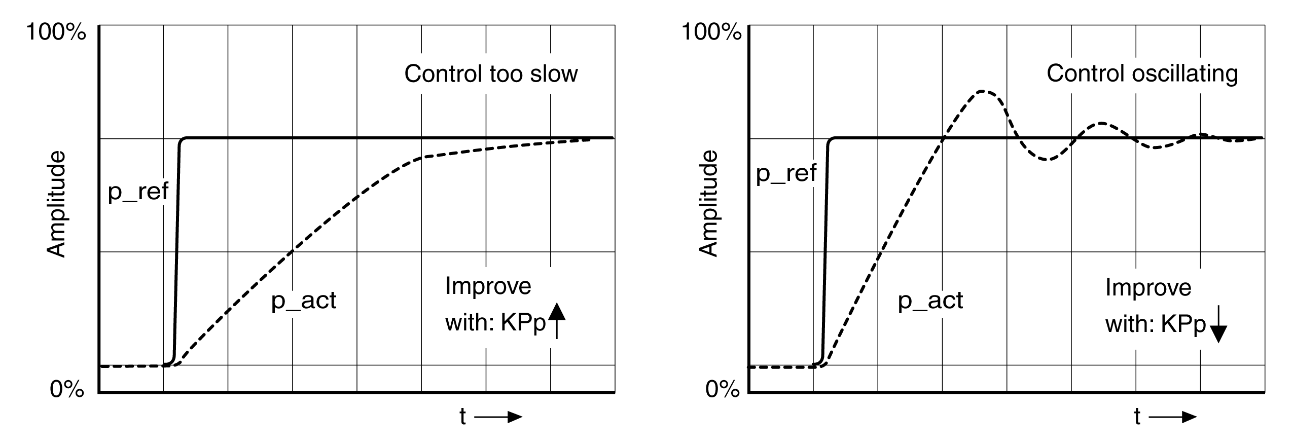
When tuning the position controller, you must optimize the P gain CTRL1_KPp (CTRL2_KPp):
oCTRL1_KPp (CTRL2_KPp) too high: Overshooting, instability
oCTRL1_KPp (CTRL2_KPp) too low: High position deviation
|
Parameter name HMI menu HMI name |
Description |
Unit Minimum value Factory setting Maximum value |
Data type R/W Persistent Expert |
Parameter address via fieldbus |
|---|---|---|---|---|
|
(ConF) → (drC-) ( PP1) |
Position controller P gain. The default value is calculated.
In the case of switching between the two control loop parameter sets, the values are changed linearly over the time defined in the parameter CTRL_ParChgTime. Type: Unsigned decimal - 2 bytes Write access via Sercos: CP2, CP3, CP4 In increments of 0.1 1/s. Modified settings become effective immediately. |
1/s 2.0 - 900.0 |
UINT16 R/W per. - |
Modbus 4614 IDN P-0-3018.0.3 |
|
(ConF) → (drC-) ( PP2) |
Position controller P gain. The default value is calculated.
In the case of switching between the two control loop parameter sets, the values are changed linearly over the time defined in the parameter CTRL_ParChgTime. Type: Unsigned decimal - 2 bytes Write access via Sercos: CP2, CP3, CP4 In increments of 0.1 1/s. Modified settings become effective immediately. |
1/s 2.0 - 900.0 |
UINT16 R/W per. - |
Modbus 4870 IDN P-0-3019.0.3 |
The step function moves the motor at constant velocity until the specified time has expired.
|
|
|
UNINTENDED MOVEMENT |
|
oOnly start the system if there are no persons or obstructions in the zone of operation. oVerify that the values for the velocity and the time do not exceed the available movement range. oVerify that a functioning emergency stop push-button is within reach of all persons involved in the operation. |
|
Failure to follow these instructions can result in death, serious injury, or equipment damage. |
Setting the Reference Value Signal
oSelect Position Controller as the reference value in the commissioning software.
oSet the reference value signal:
oSignal type: "Step"
oSet the amplitude to approx. 1/10 motor revolution.
The amplitude is entered in user-defined units. With the default scaling, the resolution is 16384 user-defined units per motor revolution.
oSelect the values in the box General Trace Parameters:
oReference position of position controller _p_refusr (_p_ref)
oActual position of position controller _p_actusr (_p_act)
oActual velocity _v_act
oReference value current _Iq_ref
Optimizing the Position Controller Value
oTrigger a step function with the default controller values.
oAfter the first test, verify the values achieved for _v_act and _Iq_ref for current control and velocity control. The values must not reach the current and velocity limitation range.
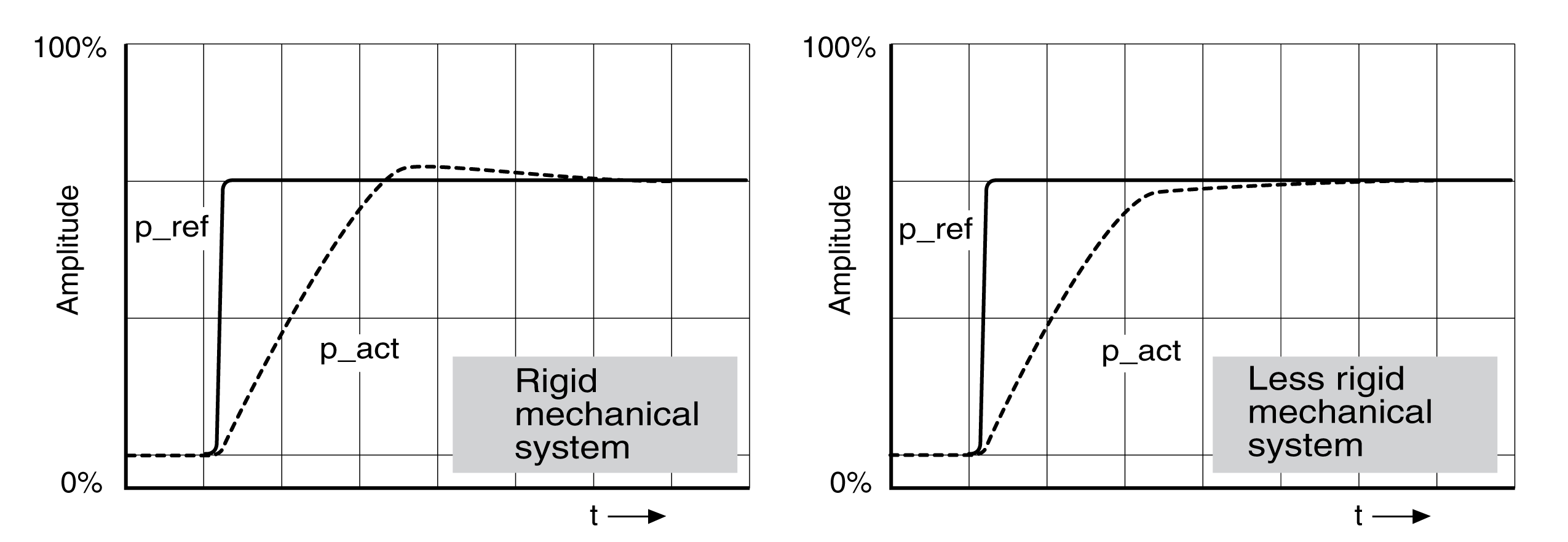
Step responses of a position controller with good control performance

The p gain setting CTRL1_KPp (CTRL2_KPp) is optimal if the reference value is reached rapidly and with little or no overshooting.
If the control performance does not correspond to the curve shown, change the P gain CTRL1_KPp (CTRL2_KPp) in increments of approximately 10% and trigger another step function.
oIf the control tends to oscillate: Use a lower KPp value.
oIf the actual value is too slow reaching the reference value: Use a higher KPp value.
Optimizing inadequate position controller settings
