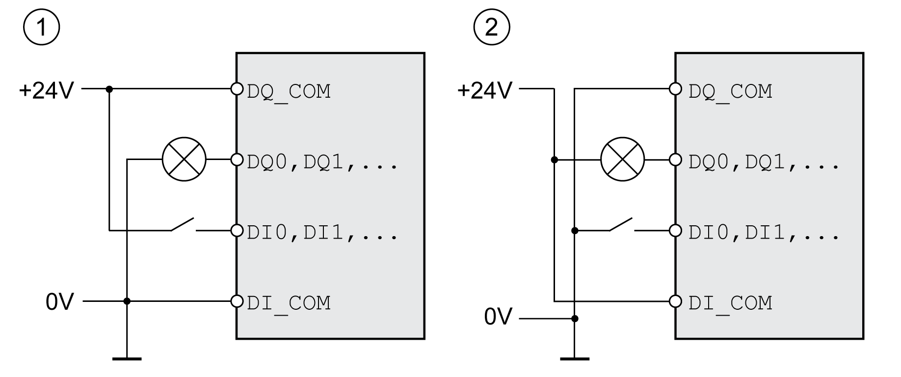
The digital inputs and outputs of this product can be wired for positive logic or negative logic.

|
Logic type |
Active state |
|---|---|
|
(1) Positive logic |
Output supplies current (source output) Current flows to the input (sink input) |
|
(2) Negative logic |
Output draws current (sink output) Current flows from the input (source input) |
Signal inputs are protected against reverse polarity, outputs are short-circuit protected. The inputs and outputs are functionally isolated.
If negative logic is used, a ground fault of a signal is detected as an On state.
|
|
|
UNINTENDED EQUIPMENT OPERATION |
|
Verify that a short-circuit of a signal cannot cause unintended equipment operation. |
|
Failure to follow these instructions can result in death, serious injury, or equipment damage. |
The logic type is determined by the wiring of DI_COM and DQ_COM. The logic type affects wiring and control of the sensors; therefore, you must determine the required value in the engineering phase in view of the application.
Special Case: Safety Function STO
The inputs for the safety function STO (inputs STO_A and STO_B) can only be wired for positive logic.