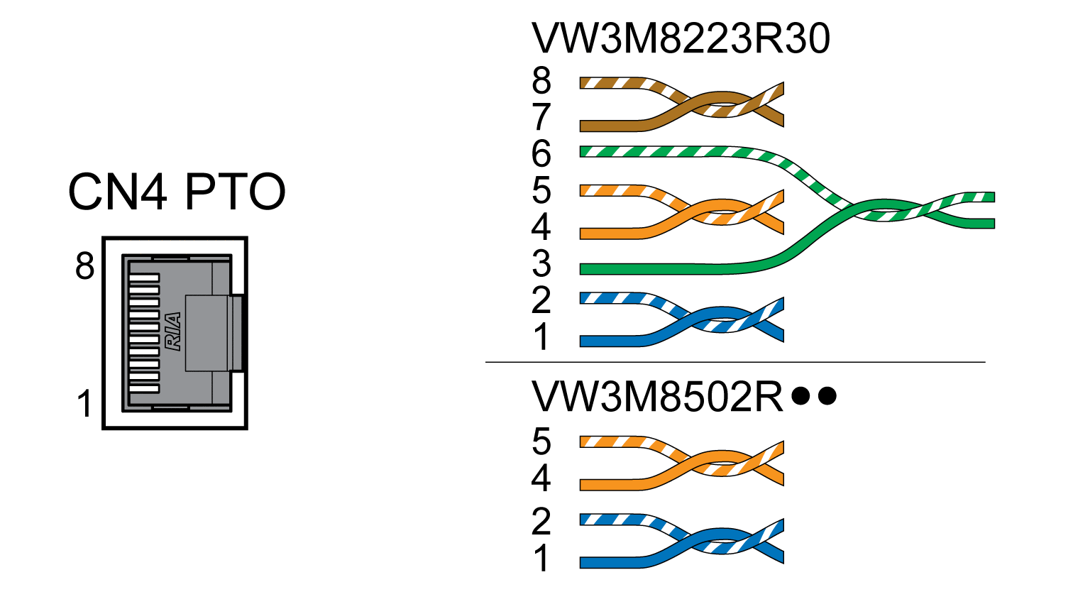
Connection PTO (CN4, Pulse Train Out)
5 V signals are available at the PTO (Pulse Train Out, CN4) output. Depending on parameter PTO_mode, these signals are ESIM signals (encoder simulation) or logically fed through PTI input signals (P/D signals, A/B signals, CW/CCW signals). The PTO output signals can be used as PTI input signals for another device. The signal level corresponds to RS422, see chapter Output PTO (CN4). The PTO output supplies 5 V signals, even if the PTI input signal is a 24 V signal.
Available with firmware version ≥V01.04.
|
Shield: |
Required, both ends grounded |
|
Twisted Pair: |
Required |
|
PELV: |
Required |
|
Cable composition: |
8 * 0.14 mm2 (8 * AWG 24) |
|
Maximum cable length: |
100 m (328 ft) |
Use pre-assembled cables to reduce the risk of wiring errors, see chapter Accessories and Spare Parts.
Wiring diagram Pulse Train Out (PTO)

|
Pin |
Signal |
Pair |
Meaning |
|---|---|---|---|
|
1 |
ESIM_A |
2 |
ESIM channel A |
|
2 |
ESIM_A |
2 |
ESIM channel A, inverted |
|
4 |
ESIM_B |
1 |
ESIM channel B |
|
5 |
ESIM_B |
1 |
ESIM channel B, inverted |
|
3 |
ESIM_I |
3 |
ESIM index pulse |
|
6 |
ESIM_I |
3 |
ESIM index pulse, inverted |
|
7 |
|
4 |
Reference potential |
|
8 |
|
4 |
Reference potential |
PTO: Logically Fed Through PTI Signals
At the PTO output, the PTI input signals can be made available again to control a subsequent device (daisy chain). Depending on the input signal, the output signal can be of type P/D signal, A/B signal or CW/CCW signal. The PTO output supplies 5 V signals.
oConnect the connector to CN4. Verify correct pin assignment.
oVerify that the connector locks snap in properly.