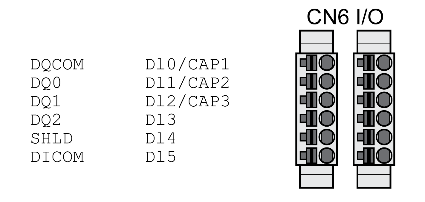
Connection Digital Inputs and Outputs (CN6)
The device has configurable inputs and configurable outputs. The standard assignment and the configurable assignment depend on the selected operating mode. For more information, see chapter Digital Inputs and Outputs.
|
Shield: |
- |
|
Twisted Pair: |
- |
|
PELV: |
Required |
|
Cable composition: |
0.25 mm2, (AWG 22) |
|
Maximum cable length: |
30 m (98.4 ft) |
Properties of Connection Terminals CN6
|
Characteristic |
Unit |
Value |
|---|---|---|
|
Connection cross section |
mm2 (AWG) |
0.2 ... 1.0 (24 ... 16) |
|
Stripping length |
mm (in) |
10 (0.39) |
|
Signal |
Meaning |
|---|---|
|
DQ_COM |
Reference potential to DQ0 ... DQ4 |
|
DQ0 |
Digital output 0 |
|
DQ1 |
Digital output 1 |
|
DQ2 |
Digital output 2 |
|
SHLD |
Shield connection |
|
DI_COM |
Reference potential to DI0 ... DI5 |
|
DI0/CAP1 |
Digital input 0 / Capture input 1 |
|
DI1/CAP2 |
Digital input 1 / Capture input 2 |
|
DI2/CAP3(1) |
Digital input 2 / Capture input 3(1) |
|
DI3 |
Digital input 3 |
|
DI4 |
Digital input 4 |
|
DI5 |
Digital input 5 |
|
(1) Available with hardware version ≥RS03 |
|
The connectors are coded. Verify correct assignment when connecting them.
The configuration and the standard assignment of the inputs and outputs are described in chapter Digital Inputs and Outputs.
Connecting the Digital Inputs/Outputs
oWire the digital connections to CN6.
oGround the shield to SHLD.
oVerify that the connector locks snap in properly.