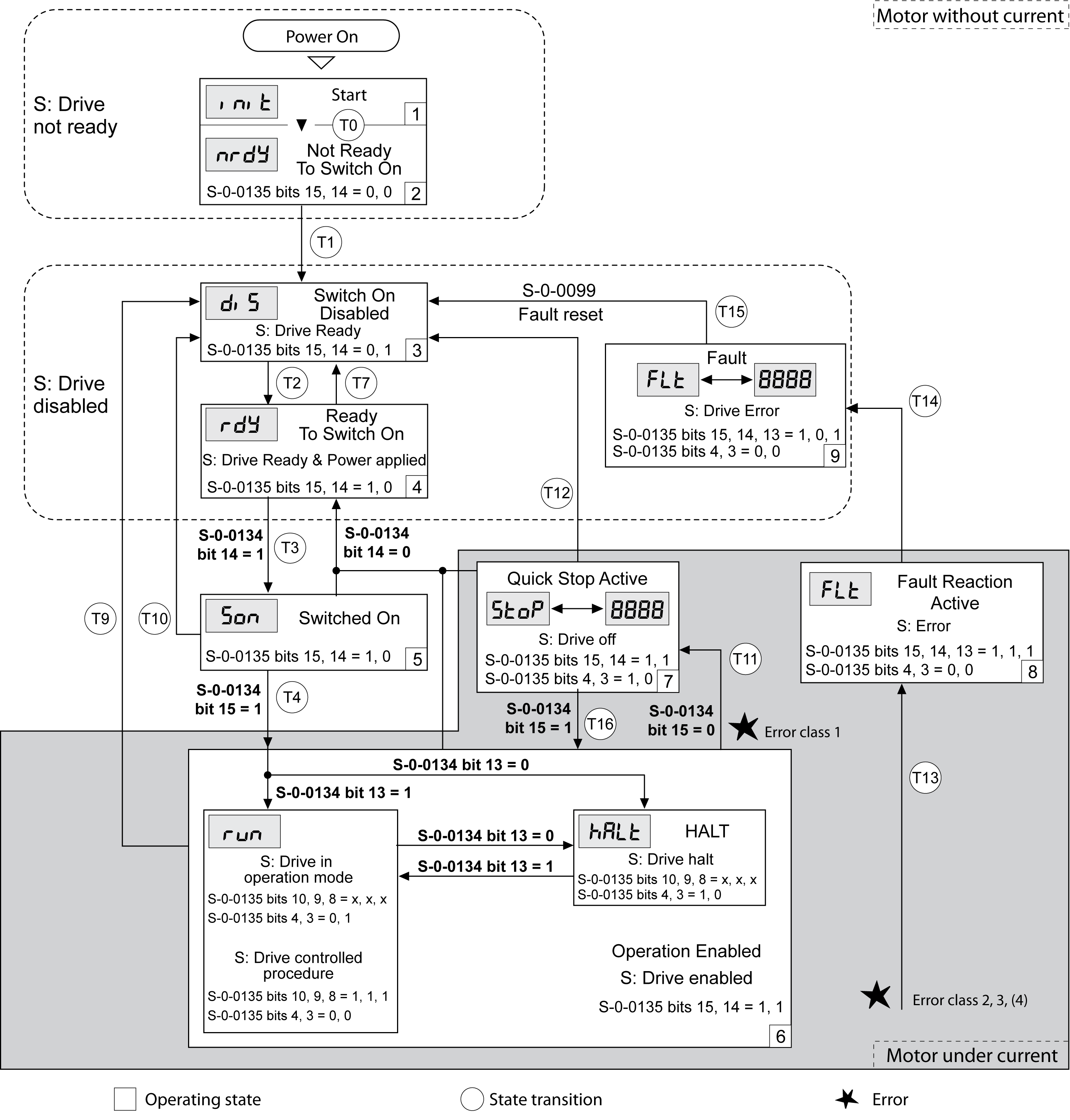
State Diagram and State Transitions
When the product is powered on and when an operating mode is started, the product goes through a number of operating states.
The state diagram (state machine) shows the relationships between the operating states and the state transitions.
The operating states are internally monitored and influenced by monitoring functions.
|
Operating state |
Description |
|---|---|
|
1 Start |
Electronics are initialized |
|
2 Not Ready To Switch On |
The power stage is not ready to switch on |
|
3 Switch On Disabled |
Impossible to enable the power stage |
|
4 Ready To Switch On |
The power stage is ready to switch on. |
|
5 Switched On |
Power stage is switched on |
|
6 Operation Enabled |
Power stage is enabled Selected operating mode is active |
|
7 Quick Stop Active |
"Quick Stop" is being executed |
|
8 Fault Reaction Active |
Error response is active |
|
9 Fault |
Error response terminated Power stage is disabled |
The errors are classified according to the following error classes:
|
Error class |
State transition |
Error response |
Resetting an error message |
|---|---|---|---|
|
0 |
- |
No interruption of the movement |
Function "Fault Reset" |
|
1 |
T11 |
Stop movement with "Quick Stop" |
Function "Fault Reset" |
|
2 |
T13, T14 |
Stop movement with "Quick Stop" and disable the power stage when the motor has come to a standstill |
Function "Fault Reset" |
|
3 |
T13, T14 |
Disable the power stage immediately without stopping the movement first |
Function "Fault Reset" |
|
4 |
T13, T14 |
Disable the power stage immediately without stopping the movement first |
Power cycle |
The state transition T13 (error class 2, 3 or 4) initiates an error response as soon as an internal occurrence signals an error to which the device must react.
|
Error class |
Response |
|---|---|
|
2 |
Movement is stopped with "Quick Stop" Holding brake is applied Power stage is disabled |
|
3, 4 or Safety function STO |
Power stage is immediately disabled |
An error can be triggered by a temperature sensor, for example. The drive cancels the movement and triggers an error response. Subsequently, the operating state changes to 9 Fault.
A "Fault Reset" resets an error message.
In the event of a "Quick Stop" triggered by a detected error of class 1 (operating state 7 Quick Stop Active), a "Fault Reset" causes a direct transition to operating state 6 Operation Enabled.
State transitions are triggered by an input signal, a fieldbus command or as a response to a monitoring function.
|
State transition |
Operating state |
Condition / event(1) |
Response |
|---|---|---|---|
|
T0 |
1-> 2 |
oDevice electronics successfully initialized |
|
|
T1 |
2-> 3 |
oParameter successfully initialized |
|
|
T2 |
3 -> 4 |
oNo undervoltage and Encoder successfully checked and Actual velocity: <1000 RPM and STO signals = +24V |
|
|
T3 |
4 -> 5 |
oRequest for enabling the power stage |
|
|
T4 |
5 -> 6 |
oRequest for ‘Drive ON’ |
Power stage is enabled. User parameters are checked. Holding brake is released (if available). |
|
T7 |
4 -> 3 |
oUndervoltage oSTO signals = 0V oActual velocity: >1000 RPM (for example by external driving force) |
- |
|
T9 |
6 -> 3 |
oRequest for disabling the power stage |
|
|
T10 |
5 -> 3 |
oRequest for disabling the power stage |
|
|
T11 |
6 -> 7 |
oError of error class 1 |
Movement is canceled with "Quick Stop". |
|
T12 |
7 -> 3 |
oRequest for disabling the power stage |
Power stage is disabled immediately, even if "Quick Stop" is still active. |
|
T13 |
x -> 8 |
oError of error classes 2, 3 or 4 |
Error response is carried out, see "Error Response". |
|
T14 |
8 -> 9 |
oError response terminated (error class 2) oError of error classes 3 or 4 |
|
|
T15 |
9 -> 3 |
oFunction: "Fault Reset" |
Error is reset (cause of error must have been corrected). |
|
T16 |
7 -> 6 |
oFunction: "Fault Reset" |
In the event of a "Quick Stop" triggered by a detected error of class 1, a "Fault Reset" causes a direct transition to the operating state 6 Operation Enabled. |
|
(1) In order to trigger a state transition it is sufficient if one condition is met |
|||