Introduction to Network Variables List (NVL)
The Network Variables List (NVL) feature consists of a fixed list of variables that can be sent or received through a communication network. This enables data exchange within a network via network variables, if supported by the controller (target system).
The list must be defined in the sender and in the receiver controllers (and can be handled in a single or in multiple projects). Their values are transmitted via broadcasting through User Datagram Protocol (UDP) datagrams. UDP is a connectionless Internet communications protocol defined by IETF RFC 768. This protocol facilitates the direct transmission of datagrams on Internet Protocol (IP) networks. UDP/IP messages do not expect a response, and are therefore ideal for applications in which dropped packets do not require retransmission (such as streaming video and networks that demand real-time performance).
The NVL functionality is a powerful feature of EcoStruxure Machine Expert. It allows you to share and monitor data between controllers and their applications. However, there are no restrictions as to the purpose of the data exchanged between controllers, including, but not limited to, attempting machine or process interlocking or even controller state changes.
NOTE: The type of the network variable is not shared between different controllers. You have to ensure that the used types have the same definition on all devices; otherwise NVL communication is not possible. This applies, for example, to the types SEC.ETH_R_STRUCT or SEC.PLC_R_STRUCT. They are available by default in various controllers with different size or fields.
Only you, the application designer and/or programmer, can be aware of all the conditions and factors present during operation of the machine or process and, therefore, only you can determine the proper communication strategies, interlocks and related safeties necessary for your purposes in exchanging data between controllers using this feature. Strict care must be taken to monitor this type of communication feature, and to be sure that the design of the machine or process will not present safety risks to people or property.
|
|
|
LOSS OF CONTROL |
|
oThe designer of any control scheme must consider the potential failure modes of control paths and, for certain critical control functions, provide a means to achieve a safe state during and after a path failure. Examples of critical control functions are emergency stop and overtravel stop, power outage and restart. oSeparate or redundant control paths must be provided for critical control functions. oSystem control paths may include communication links. Consideration must be given to the implications of unanticipated transmission delays or failures of the link. oObserve all accident prevention regulations and local safety guidelines.1 oEach implementation of this equipment must be individually and thoroughly tested for proper operation before being placed into service. |
|
Failure to follow these instructions can result in death, serious injury, or equipment damage. |
1 For additional information, refer to NEMA ICS 1.1 (latest edition), "Safety Guidelines for the Application, Installation, and Maintenance of Solid State Control" and to NEMA ICS 7.1 (latest edition), "Safety Standards for Construction and Guide for Selection, Installation and Operation of Adjustable-Speed Drive Systems" or their equivalent governing your particular location.
You can use Diagnostic and Error Management function blocks as well as network properties parameters to monitor the health, status and integrity of communications using this feature. This feature was designed for data sharing and monitoring and cannot be used for critical control functions.
The network variables to be exchanged are defined in the following 2 types of lists:
oGlobal Variables Lists (GVL) in a sending controller (sender)
oGlobal Network Variables List (GNVL) in a receiving controller (receiver)
The corresponding GVL and GNVL contain the same variable declarations. You can view their contents in the respective editor that opens after double-clicking the GVL or GNVL node in the Devices pane.
A GVL contains the network variables of a sender. In the Network properties of the sender, protocol and transmission parameters are defined. According to these settings, the variable values are broadcasted within the network. They can be received by all controllers that have a corresponding GNVL.
NOTE: For network variables exchange, the respective network libraries must be installed. This is done automatically for the standard network type UDP as soon as the network properties for a GVL are set.
Network variables are broadcasted from the GVL (sender) to one or more GNVL (receivers). For each controller you can define GVLs as well as GNVLs. Thus each controller can act as sender as well as receiver.
A sender GVL can be provided by the same or by another project. So, when creating a GNVL, the sender GVL can either be chosen from a selection list of all available GVLs within the network, or it can be read from an export file, which previously has been generated (for example, by using the Link to File dialog box) from the GVL.
NOTE: An export file is needed if the sender GVL to be used is defined within another project.
The following table shows the list of controllers that support the network variables list (NVL) functionality:
|
Function Name |
M241 |
M251 |
M258 LMC058 |
M262 |
LMC Eco LMC Pro LMC Pro2 |
|---|---|---|---|---|---|
|
Network Variables List |
Yes |
Yes |
Yes |
Yes |
Yes |
The figure shows a network consisting of 1 sender and the maximum of 7 receivers:
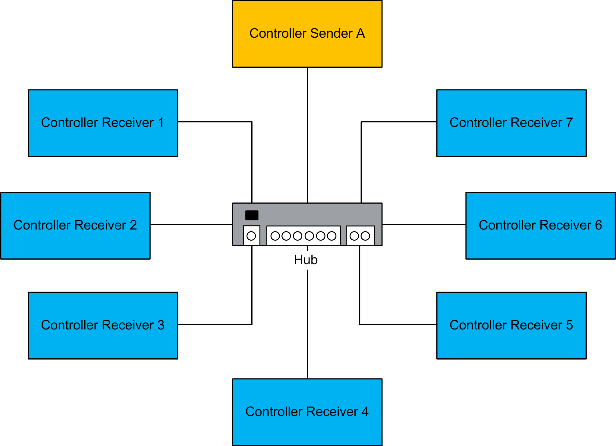
Controller Sender A: Sender with the global variables list (GVL) and receiver controller with global network variables lists (GNVLs)
Controller Receiver 1...7: Receivers (with GNVL) from A and sender controller (GVL) only for A
