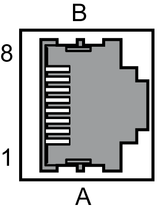
At the motor encoder connection, the measuring system, which records the axis position, is connected.

|
Pin |
Designation |
Meaning |
|---|---|---|
|
1 |
Cos |
Cosine track axis A/B |
|
2 |
RefCos |
Reference signal cosine axis A/B |
|
3 |
Sin |
Sine track axis A/B |
|
4 |
RS-485+ |
Positive RS-485 signal axis A/B |
|
5 |
RS485- |
Negative RS-485 signal axis A/B |
|
6 |
RefSin |
Reference signal sine axis A/B |
|
7 |
N.C. |
Reserved |
|
8 |
N.C. |
Reserved |
|
A |
P10V |
Supply voltage encoder A/B |
|
B |
GND |
Mass A/B |
NOTE: By usage of the 5 V encoder adapter it is also possible to connect encoder with 5 V supply voltage to the drive.
oThe encoder must be connected to the servo amplifier according to the pin configuration of the encoder connector, which can be found in the table above. Special attention must be paid to the shielding; the shielding must be connected at the servo amplifier and motor side.
oIf it is an encoder without HIPERFACE interface, pins 4 and 5 do not have to be connected.
oWhen connecting the encoder, the instructions and recommendations of the operating manual of the servo amplifier are also to be considered.
NOTE: Especially for the encoder type TTK70 by SICK / Stegmann a Schneider Electric standard cable is available.